Optical coherence tomography device having a plurality of calibration reflecting surfaces

a coherence tomography and reflecting surface technology, applied in the field of optical coherence tomography, can solve the problems of inability to prepare calibration data, inability to accurately predict the calibration value of the device, and the coherence waveform acquired contains a frequency error, so as to achieve the effect of suppressing complication of device configuration and easy preparation of calibration data

Active Publication Date: 2016-06-07
TOMEY CORP
View PDF20 Cites 0 Cited by
  • Summary
  • Abstract
  • Description
  • Claims
  • Application Information

AI Technical Summary

Benefits of technology

[0007]The specification of this application will disclose an optical tomographic device that has a simple device configuration and yet can easily prepare data for calibration.
[0009]This tomographic device is provided with the calibration optical system for correcting the nonlinearity of a wavelength sweeping of the light source. This calibration optical system guides light branched from the measurement optical system or the reference optical system to the calibration reflecting surface, which is herein a reflecting surface for calibration, and guides reflected light from the calibration reflecting surface. Then, the interfering light for calibration is formed by the reflected light from the calibration optical system and reference light from the reference optical system, and the interfering light for calibration is received by the light-receiving element. The arithmetic logic unit prepares calibration data based on the interfering light for calibration. Since this tomographic device is provided with the calibration optical system having the calibration reflecting surface, it is not necessary to attach and detach a calibration jig to prepare calibration data. As a result, the calibration data can be easily prepared. In addition, the interfering light for calibration and the interfering light for measurement are synthesized and detected by the same light-receiving element. For this reason, the optical systems share one or more components therein for generating / detecting the interfering light for calibration and the interfering light for measurement. Therefore, complication of the device configuration can be suppressed.

Problems solved by technology

A tomographic device of the SS-OCT type can acquire data fast since a wavelength sweeping light source is used, but on the other hand there is a problem that the wavelength of light outputted from the wavelength sweeping light source does not linearly change with time.
As a result, if an interference signal is sampled at regular time intervals, a coherence waveform acquired contains a frequency error.
As a result, the data for calibration cannot easily be prepared.
Since the two interference optical systems must be mounted on a single tomographic device, there is such a problem that the device configuration becomes complicated.

Method used


Image

  • Optical coherence tomography device having a plurality of calibration reflecting surfaces
  • Optical coherence tomography device having a plurality of calibration reflecting surfaces
  • Optical coherence tomography device having a plurality of calibration reflecting surfaces

Examples


embodiment

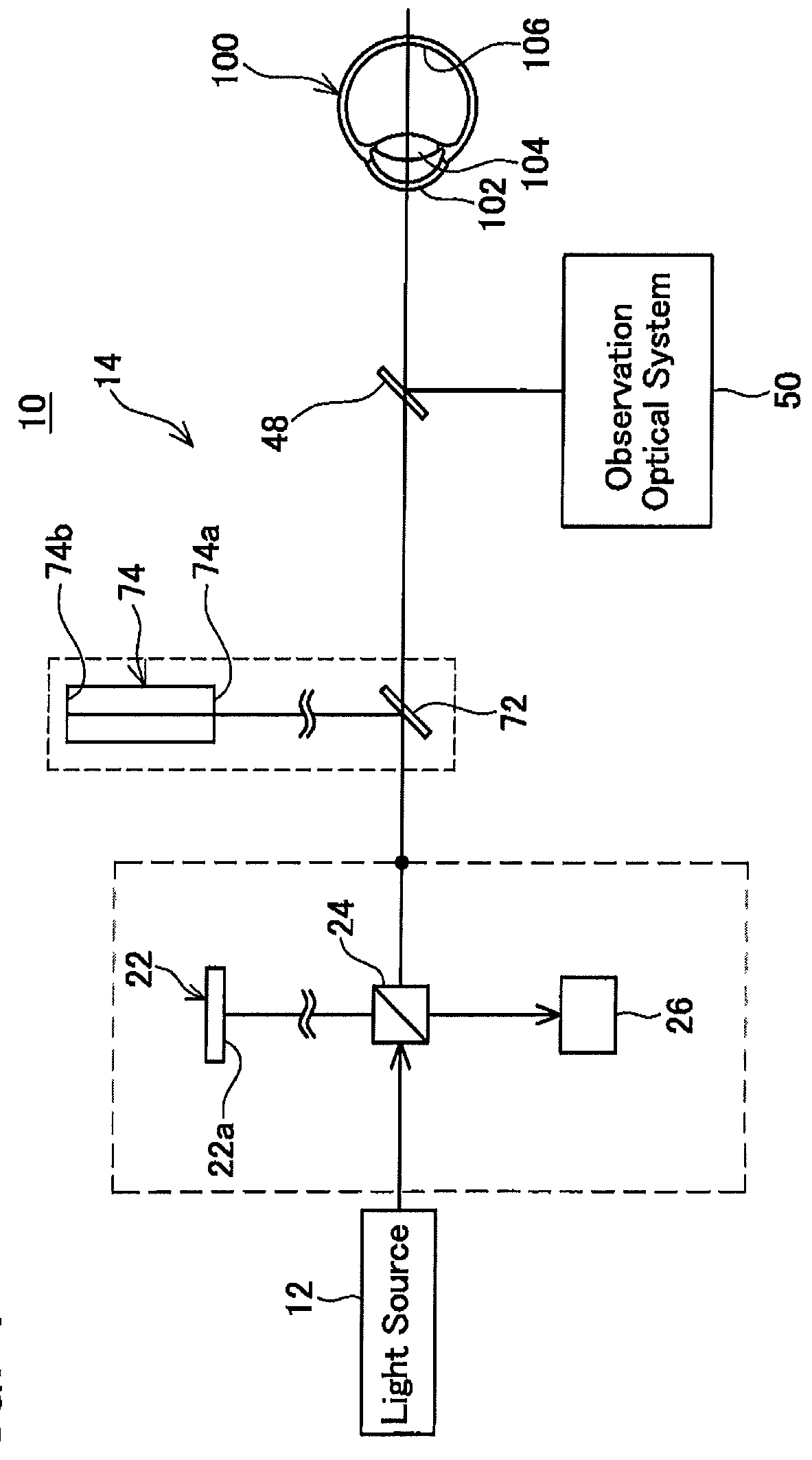
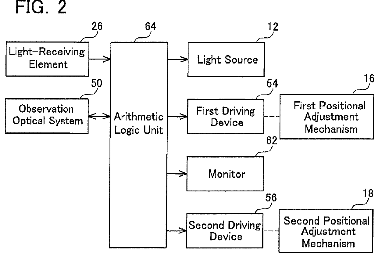
[0021]As shown in FIG. 1, an ophthalmic device of the embodiment has a measuring unit 10 for examining a subject's eye 100. The measuring unit 10 has an interference optical system 14 for causing reflected light reflected from the subject's eye 100 and reference light to interfere with each other, an observation optical system 50 for observing an anterior eye part of the subject's eye 100, and an alignment optical system (not shown) for aligning the measuring unit 10 with the subject's eye 100 such that a predetermined positional relationship is made therebetween. As the alignment optical system, one used in a known ophthalmic device can be used, so the description of the details thereof is omitted.

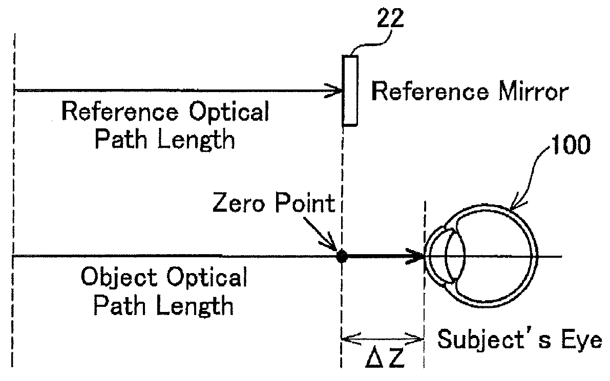
[0022]The interference optical system 14 is composed of a light source 12, a measurement optical system (24, 72, 48) that irradiates light from the light source 12 into an inside of the subject's eye and guides reflected light therefrom, a reference optical system (24, 22) that irradiates...


PUM


Abstract

Provided is an optical tomographic device including a measurement optical system that irradiates light from a light source to inside a subject and guides reflected light therefrom; a reference optical system that guides the light from the light source as reference light; a calibration optical system that irradiates a calibration reflecting surface with light from the light source, and guides the reflected light reflected by the calibration reflecting surface; a light-receiving element that receives the interfering light for measurement formed by synthesizing the reflected light guided by the measurement optical system and the reference light, and the interfering light for calibration formed by synthesizing the reflected light guided by the calibration optical system and the reference light; and an arithmetic logic unit that corrects the received interfering light for measurement by using an analysis result obtained by analyzing the received the interfering light for calibration.

Description

CROSS-REFERENCE TO RELATED APPLICATION[0001]This application claims priority to Japanese Patent Application No. 2013-96752 filed on May 2, 2013, the contents of which are hereby incorporated by reference into the present application.TECHNICAL FIELD[0002]The present teachings relate to an optical coherence tomography.DESCRIPTION OF RELATED ART[0003]Tomographic devices for producing tomograms through the use of optical coherence are being developed (for example, an ophthalmic device for examining a subject's eye). Tomographic devices of this type include a Fourier-domain type using a wavelength sweeping light source (a so-called SS-OCT type). A tomographic device of the SS-OCT type can acquire data fast since a wavelength sweeping light source is used, but on the other hand there is a problem that the wavelength of light outputted from the wavelength sweeping light source does not linearly change with time. As a result, if an interference signal is sampled at regular time intervals, a...

Claims


Application Information

Patent Timeline
Patent Type & Authority Patents(United States)
IPC IPC(8): G01B9/02A61B3/10
CPCG01B9/02091A61B3/102G01B9/02072A61B2560/0228G01B9/02004G01B2290/60G01B9/02069G01B9/0203G01B9/02074G01B9/02092
Inventor SUGIYAMA, SATOSHINOZAWA, YUJI
Owner TOMEY CORP
Why Eureka
Try Eureka