Clutch apparatus for a hydrostatic continuously variable transmission and transmission incorporating same

a continuously variable transmission and clutch valve technology, applied in the direction of fluid couplings, gearings, couplings, etc., can solve the problems of limiting the manufacturer's ability to make the device smaller and compact, limiting the manufacturer's ability to limit the cost, and a relatively large structure of the known clutch valve, so as to achieve easy maintenance of the governor mechanism, simple device configuration, and easy reduction in size

Inactive Publication Date: 2005-07-07
HONDA MOTOR CO LTD
View PDF4 Cites 11 Cited by
  • Summary
  • Abstract
  • Description
  • Claims
  • Application Information

AI Technical Summary

Benefits of technology

[0018] According to the clutch device of the present invention configured as above, the valve spool is moved in the internal bore by the governor force generated by the governor mechanism, so as to make or interrupt the communication between the high pressure side oil passage and the low pressure side oil passage, so that the operation of the clutch can be controlled mechanically, the device configuration is simple and easy to reduce in size, and the operation of the clutch can be easily controlled.
[0019] Furthermore, the governor mechanism can be disposed at an end portion of the clutch assembly, so that the setting of operations and the maintenance of the governor mechanism are easy to carry out.

Problems solved by technology

The known clutch valve has had the problems of a relatively large structure and high cost, due to the need for the hydraulic governor, the actuator and the like.
However, since the operation of the clutch valve is controlled by the hydraulic pressure using the hydraulic governor, this limits the manufacturer's ability to make the device smaller and compact and to limit the cost.

Method used


Image

  • Clutch apparatus for a hydrostatic continuously variable transmission and transmission incorporating same
  • Clutch apparatus for a hydrostatic continuously variable transmission and transmission incorporating same
  • Clutch apparatus for a hydrostatic continuously variable transmission and transmission incorporating same

Examples


Embodiment Construction

[0030] Now, selected illustrative embodiments of the present invention will be described below referring to the figures.

[0031] It should be understood that only structures considered necessary for clarifying the present invention are described herein. Other conventional structures, and those of ancillary and auxiliary components of the system, are assumed to be known and understood by those skilled in the relevant art.

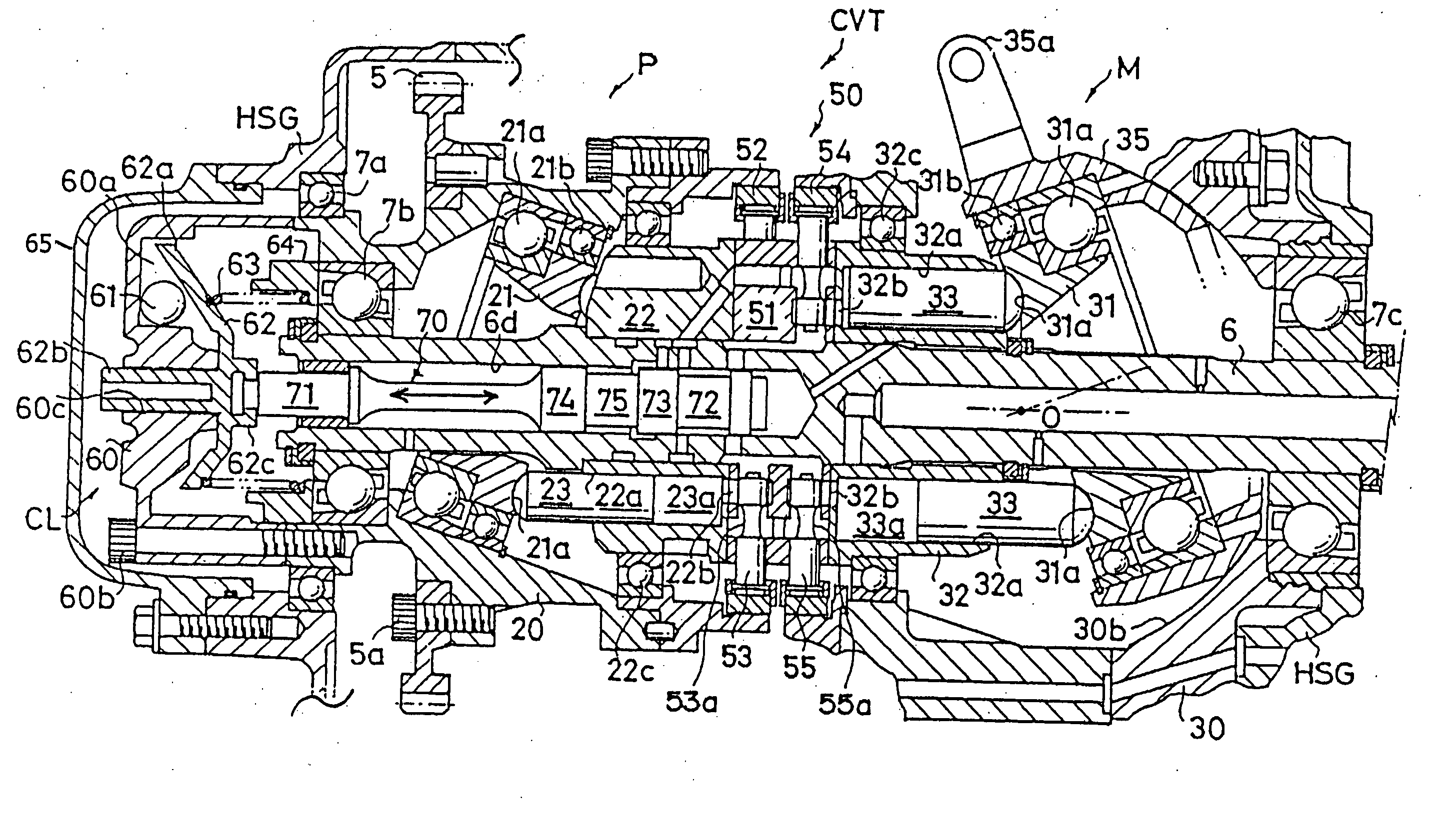
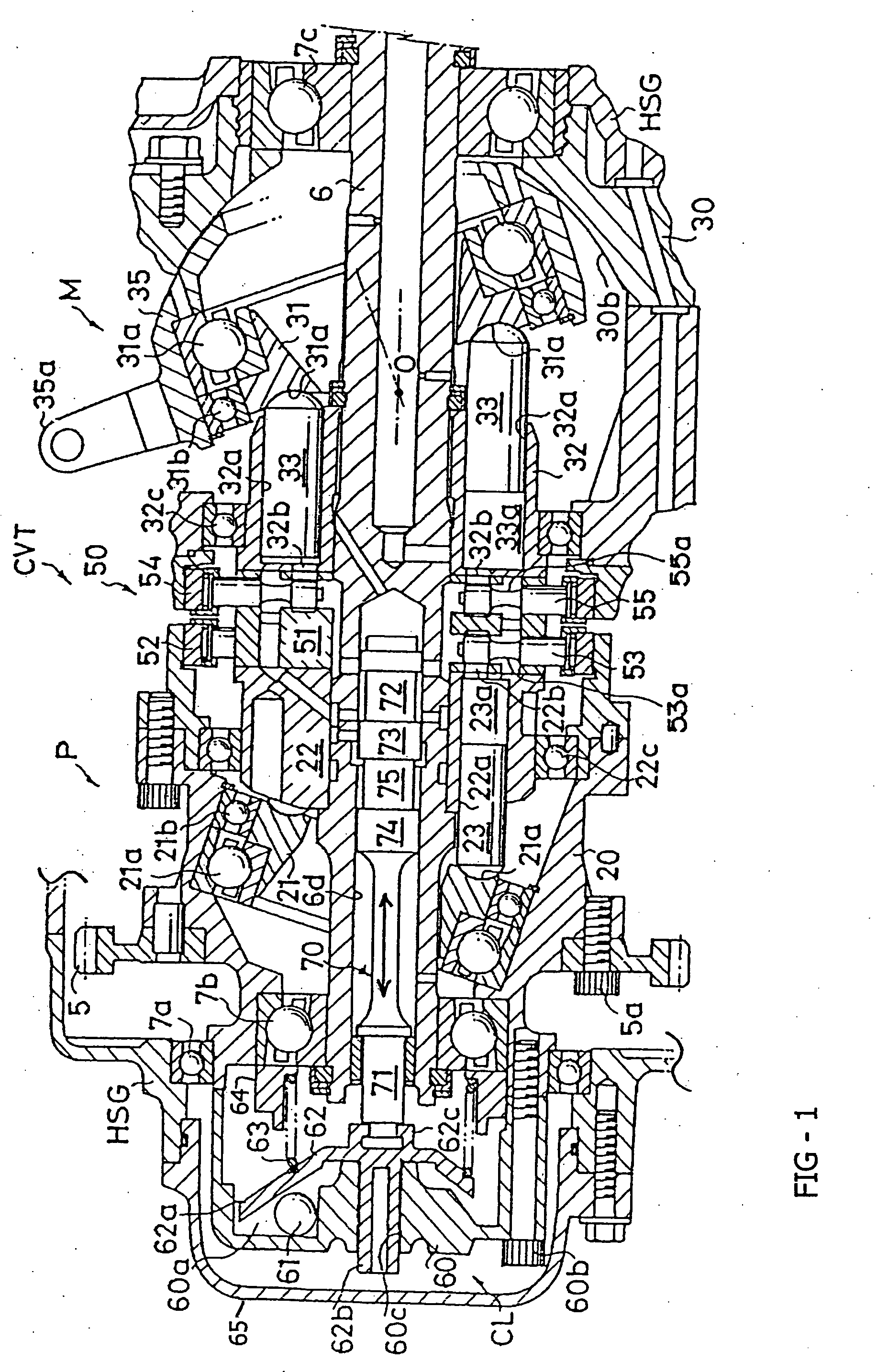
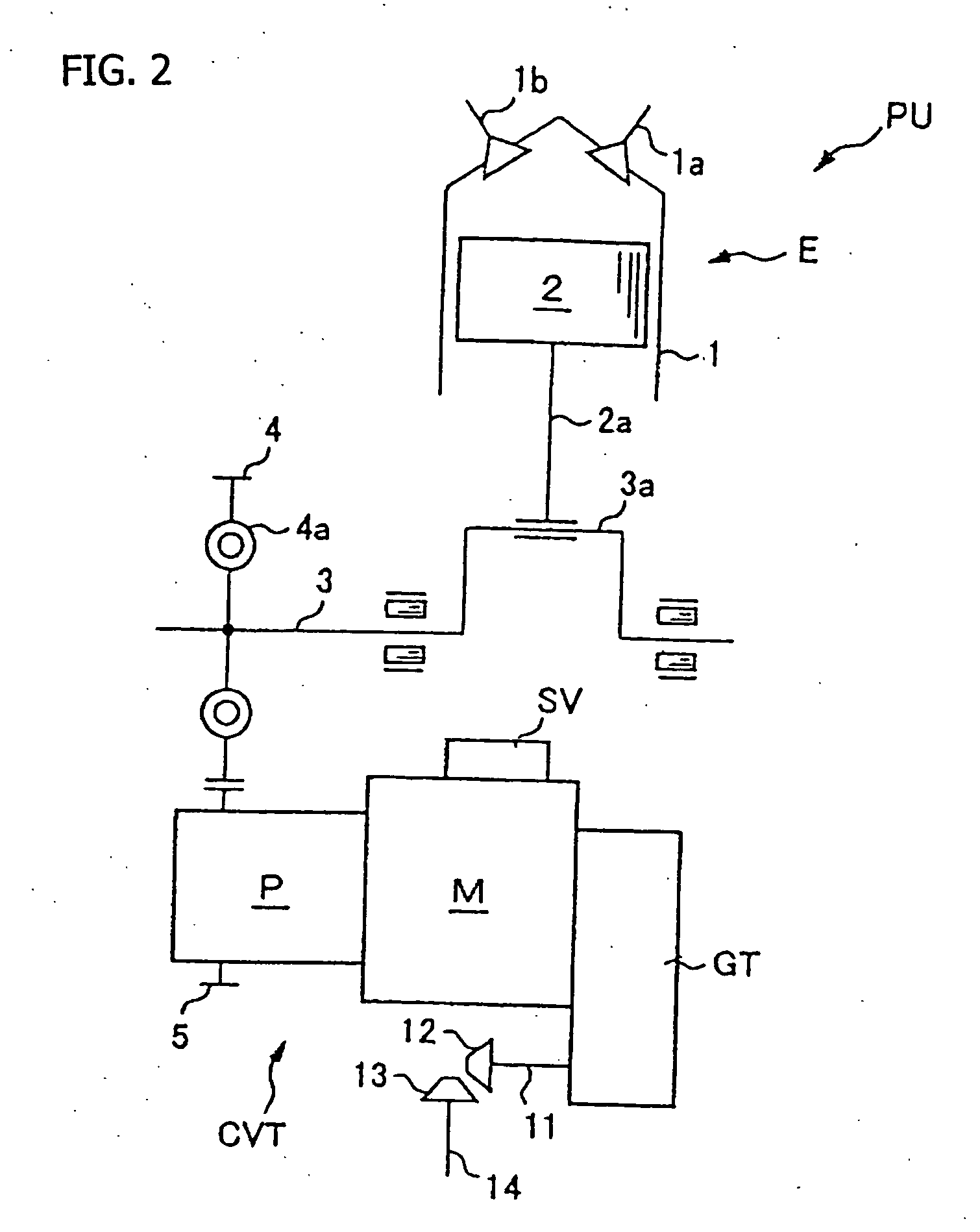
[0032]FIG. 2 is a simplified schematic diagram of a system according to the present invention, in which a powertrain unit PU includes a hydrostatic continuously variable transmission according to a first embodiment the present invention. Referring now to FIG. 2, it will be seen that the powertrain unit PU includes an engine E for generating a rotational drive force, a hydrostatic continuously variable transmission CVT for continuously varying the effective speed of the output rotation of the engine E, and a transmission gear train GT for performing direction changeov...


PUM


Abstract

A hydrostatic continuously variable transmission includes a hydraulic pump and a hydraulic motor, supported by a common support shaft, and hydraulically connectable to each other through a hydraulic circuit including an inside passage and an outside passage. A clutch device includes a valve spool, which is slidably disposed in a hollow internal bore formed in the transmission support shaft. The valve spool is operable to make or interrupt fluid communication between the inside passage and the outside passage, according to the movement thereof. A governor mechanism is mounted to a pump casing of the hydraulic pump, and the governor mechanism generates a governor force corresponding to the rotating speed of a clutch cap, by use of centrifugal force generated by the rotation thereof. The valve spool is effectively moved in the hollow internal bore, using the governor force generated from the governor mechanism, to engage or disengage the clutch.

Description

CROSS-REFERENCE TO RELATED APPLICATIONS [0001] The present invention claims priority under 35 USC 119 based on Japanese patent application No. 2003-398473, filed Nov. 15, 2003. The disclosure of Japanese patent application No. 2003-398473 is incorporated by reference. BACKGROUND OF THE INVENTION [0002] 1. Field of the Invention [0003] The present invention relates to a hydrostatic continuously variable transmission including a hydraulic pump and a hydraulic motor connected to each other through a hydraulic closed circuit, and configured so that the capacity of the hydraulic pump or the hydraulic motor is variably controlled, to vary the speed of input rotation of the hydraulic pump and to take out the speed-varied rotation as output rotation of the hydraulic motor. More particularly, the present invention relates to a clutch device for making and interrupting the communication between a high pressure side oil passage and a low pressure side oil passage, constituting the hydraulic cl...

Claims


Application Information

Patent Timeline
Patent Type & Authority Applications(United States)
IPC IPC(8): F16H39/14F16H61/14F16H61/26F16H61/40F16H61/4043F16H61/42
CPCF16H61/14F16H39/14
Inventor YOSHIDA, YOSHIHIROYAKIGAYA, NOBUYUKIKANNO, YOSHIHISASAKAKIBARA, KENJITSUKADA, YOSHIAKIOZEKI, TAKASHINANRI, TAKEHIKO
Owner HONDA MOTOR CO LTD
Why Eureka
Try Eureka