Method and device for sealing gas in a gas compartment-equipped bag

a gas compartment and gas sealing technology, which is applied in the direction of packaging, paper/cardboard articles, and packaging goods, etc., can solve the problems of reducing appearance (wrinkles), complicated adjustment work, and complicated overall structure, and achieves the effect of simplifying the configuration of the gas sealing device, and reducing the cost of operation

Inactive Publication Date: 2015-11-19
TOYO JIDOKI CO LTD
View PDF33 Cites 13 Cited by
  • Summary
  • Abstract
  • Description
  • Claims
  • Application Information

AI Technical Summary

Benefits of technology

[0060]As seen from above, according to the present invention, the gas-discharging nozzle, hot plates, and blocking grippers used in a conventional gas sealing method are replaced by a single ultrasonic sealing device, which simplifies the configuration of the gas sealing device. Also, simplifying the configuration of the gas sealing device simplifies the work entailed by adjusting the device, which is performed when the type of gas compartment-equipped bag is changed.
[0061]Generally, in ultrasonic sealing devices, the horn is air cooled, and the anvil is either water cooled or air cooled; accordingly, when the ultrasonic oscillation is stopped, the sealed portion of the bag is cooled immediately in a state that it is being clamped by the horn and the anvil. Accordingly, wrinkles or the like that are produced in the area of the sealed portion and adversely affect the appearance or decrease the strength of the sealed portion of a bag, and other such problems can be prevented.
[0062]Also, in the present invention, when a gas is discharged into the gas compartment, the distance between the distal ends of the horn and the anvil is set to be slightly greater than the thickness of the films on both sides of the gas introduction portion, and this can restrict the inflation state of the gas introduction portion to a flat shape. In addition, a gas is discharged into the gas compartment in a state that the films on both sides of the gas introduction portion are being clamped by the distal ends of the horn and the anvil, and the gas compartment is then sealed; and in this case, the occurrence of the vertical wrinkles (such as winkles 8 illustrated in FIGS. 12A through 13B) can be prevented. This also prevents leakage of the gas from the sealed gas compartment without sacrificing the appearance of the sealed portion.

Problems solved by technology

Thus, the device that performs the methods of Japanese Patent Nos. 4683899 and 4771785 includes a movable member and its drive means in addition to the nozzle and receiver, thus making the overall structure complicated.
However, such adjustments are complicated work because there are so many places to adjust.
If the sealed portion is not cooled; however, this may result in a diminished appearance (wrinkles, etc.) in the sealed portion and nearby portions, decreasing the strength in the sealed portion or creating other problems.
These problems can be prevented if the sealed portion is clamped by a pair of cooling plates and cooled after being sealed with the hot plates; however, the installation of cooling plates (including a drive means therefor) further complicates the structure of the gas sealing device.
However, this method is only applicable when the hole or cutout is formed in the upper part of the bag (or a position above the pair of left and right grippers), due to the fact that the hole or cutout is sealed and cooled together with the bag mouth.
Also, this method is only applicable when the sealing of the gas inside the gas compartment is performed following a packaging processing step (including opening of the bag mouth, filling with the contents, etc.).
During this process, the front and back films of the gas compartment (the sealed portion) clamped by the hot plates may not flatten out, resulting in that vertical wrinkles produce in the sealed portion and adversely affecting the appearance or in that the seal is imperfect that produces a gap on the inside, and the gas inside the gas compartment leaks out through this gap.
During this process, the front and back films of the gas compartment (the blocking site) clamped by the blocking grippers may not flatten out, which can result in a gap on the inside of the gas compartment, and the gas inside the gas compartment may leak out until the site of the hole or cutout is clamped by hot plates and sealed.

Method used


Image

  • Method and device for sealing gas in a gas compartment-equipped bag
  • Method and device for sealing gas in a gas compartment-equipped bag
  • Method and device for sealing gas in a gas compartment-equipped bag

Examples


first embodiment

[0078]FIGS. 4A and 4B show a gas compartment-equipped bag 11 which is a bag equipped with a gas compartment formed in a sealed portion of a side edge of the bag (hereinafter referred to simply as the “bag 11”) for which the gas sealing method and device of the present invention is used.

[0079]The bag 11 is a bottom gusset type of self-standing bag. The bag 11 is composed of films on both the front and back sides, and a folded-over bottom film. In the upper region X of the bag 11, the front and back films are bonded together at the side edges, forming sealed portions 12 and 13. The front and back films are not bonded at the upper edge, which becomes the open bag mouth 14. In the lower region Y of the bag 11, the front and back films are bonded together at the side edges with the bottom film sandwiched in between, and the bottom film itself is also bonded at its folded-over inner side. In the middle part, the front and back films are bonded to the bottom film (the bottom film is not bo...

second embodiment

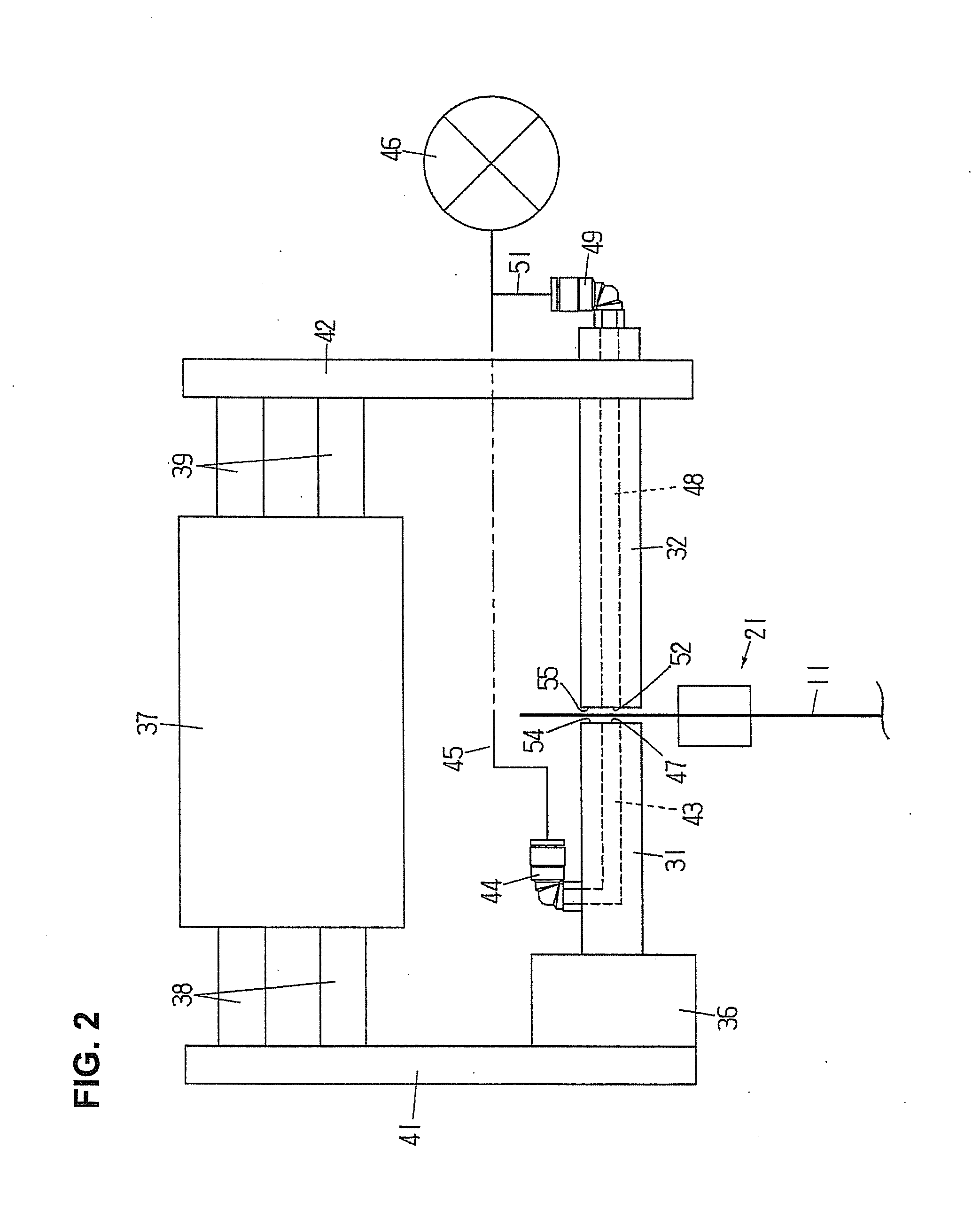
[0108]In the first embodiment above, the air cylinder 37 of the ultrasonic sealing device is a three-position type, and the horn 31 and the anvil 32 are stopped at three positions: the extended positions, the discharging positions, and the retracted positions. However, the air cylinder 37 can be a two-position type, so that the thrust that moves the horn 31 and the anvil 32 forward (which is the air pressure used) can be switched. With this two-position type cylinder as well, the discharging of the gas into the gas compartment 16 and the sealing of the gas compartment 16 (the gas introduction portion 16a) can be performed in the same manner as in the first embodiment above.

[0109]In this second embodiment that employs a two-position type cylinder, the discharging of the gas into the gas compartment 16 and the sealing of the gas compartment 16 are performed as follows, for example.

[0110]The horn 31 and the anvil 32 are moved forward under the operation of the air cylinder 37 until the...

third embodiment

[0116]In the second embodiment above, when ultrasonic sealing is performed, the thrust of the air cylinder 37 is switched to a higher thrust, so that the horn 31 and the anvil 32 are moved forward again, and the gas introduction portion 16a of the gas compartment 16 is clamped. However, if the discharging of the pressurized gas is halted instead of switching the thrust in that way, the horn 31 and the anvil 32 can be likewise moved forward again so that the gas introduction portion 16a of the gas compartment 16 is clamped thereby.

[0117]If the discharging of the pressurized gas is halted, the thrust of the air cylinder 37 immediately moves the horn 31 and the anvil 32 forward so that they clamp the gas introduction portion 16a, and leakage of the gas form the cutout 19 stops. Also, since the neck portion 16b is formed in the gas compartment 16, and the distance is narrow between the films on both sides of the neck portion 16b (widening only to the depth of the groove 24 of the grippe...


PUM

PropertyMeasurementUnit
thicknessaaaaaaaaaa
distanceaaaaaaaaaa
specific biasing forceaaaaaaaaaa

Abstract

A method and device for sealing gas in a gas compartment-equipped bag, in which pressurized gas discharge outlets (47, 52) are provided in the distal ends of a horn (31) and an anvil (32) of an ultrasonic sealing device, and such horn and anvil used for ultrasonic sealing are also used as gas-discharging nozzles. The distal ends of the horn and the anvil are placed against a cutout (19) of a gas compartment (16) of a bag, a gas is discharged into the gas compartment from the discharge outlets, the films surrounding the cutout are being clamped by the horn and the anvil while gas discharging is in progress, and then the gas compartment is ultrasonically sealed by the horn and the anvil to trap the gas inside.

Description

BACKGROUND OF THE INVENTION[0001]1. Field of the Invention[0002]The present invention relates to a method and device for sealing a gas in the gas compartment of a bag that is equipped with a gas compartment formed in the sealed portion of a side edge of the bag.[0003]2. Description of the Related Art[0004]Japanese Patent Nos. 4683899, 4771785, and 5104073 disclose a method that discharges a gas into the gas compartment of a gas compartment-equipped bag (a bag which is equipped with a gas compartment) then sealed the gas compartment. In this gas compartment-equipped bag, the gas compartment that extends in the longitudinal direction of the bag is integrally formed in the sealed portion of the side edge of the bag, and a hole or cutout that communicates the outside of the bag with the inside of the gas compartment is formed in the film that forms the gas compartment. The films on the front and back sides of the bag are laminated films, with the inner layer composed of a sealant materi...

Claims


Application Information

Patent Timeline
Patent Type & Authority Applications(United States)
IPC IPC(8): B31D5/00B29C65/08
CPCB29C65/08B31D5/0073B65B31/048B65B51/146B65B31/006B65B43/18B65B43/22B65B43/30B65B43/34B65B43/465B65B43/60B65B51/225B65B51/32B65B61/025B65B61/28B65B3/26B29C65/18B29C65/72B29C65/7841B29C65/7882B29C66/0342B29C66/1122B29C66/21B29C66/342B29C66/3452B29C66/43121B29C66/81433B29C66/8242B29C66/83221B29C66/849B29L2031/7128B29C66/81811B29C66/24221B29C66/3494B29C66/439B29C66/81431B29C66/723
Inventor HONDA, YASUYUKITONOZUKA, HIROMASA
Owner TOYO JIDOKI CO LTD
Why Eureka
Try Eureka