

Method and Device for Pivotably Driving Carriage and Tire Building System Using Same
- Summary
- Abstract
- Description
- Claims
- Application Information
AI Technical Summary
Benefits of technology
Problems solved by technology
Method used
Image

Examples
Embodiment Construction
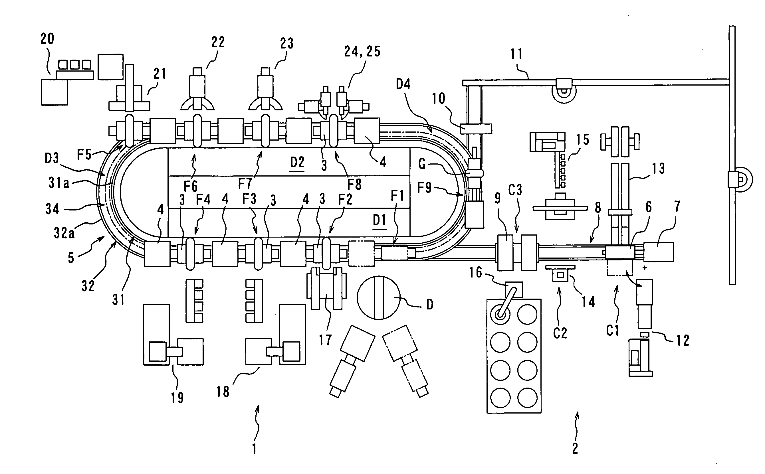
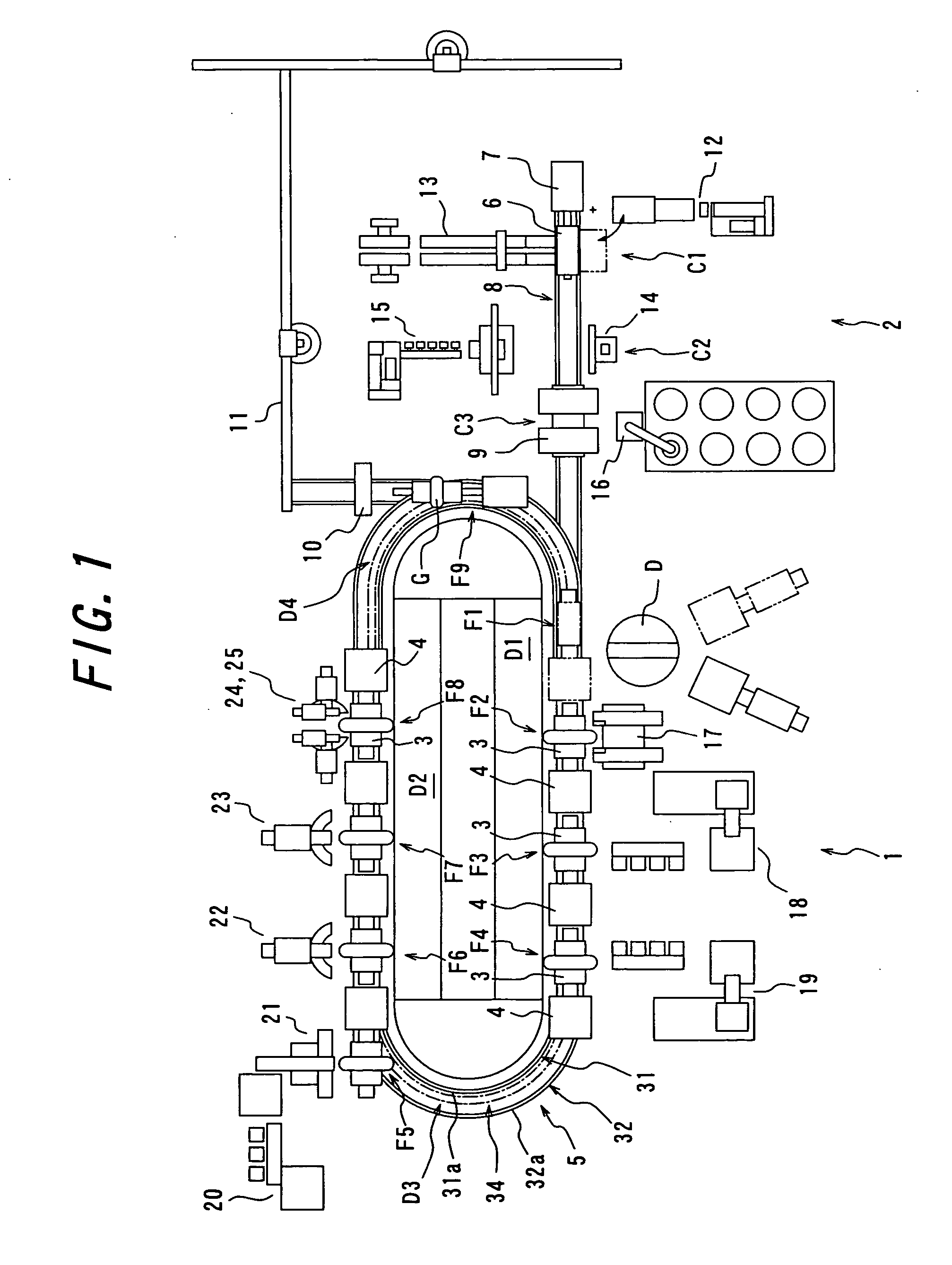
[0034] With reference to the drawings, one embodiment of the present invention will be discussed below. FIG. 1 is a schematic plan view of one embodiment of a tire building system according to the present invention showing with a pre-building system. In the figure, the reference numeral 1 denotes a tire building system according to the present invention, and the reference numeral 2 denotes a pre-building system arranged next to the tire building system 1.
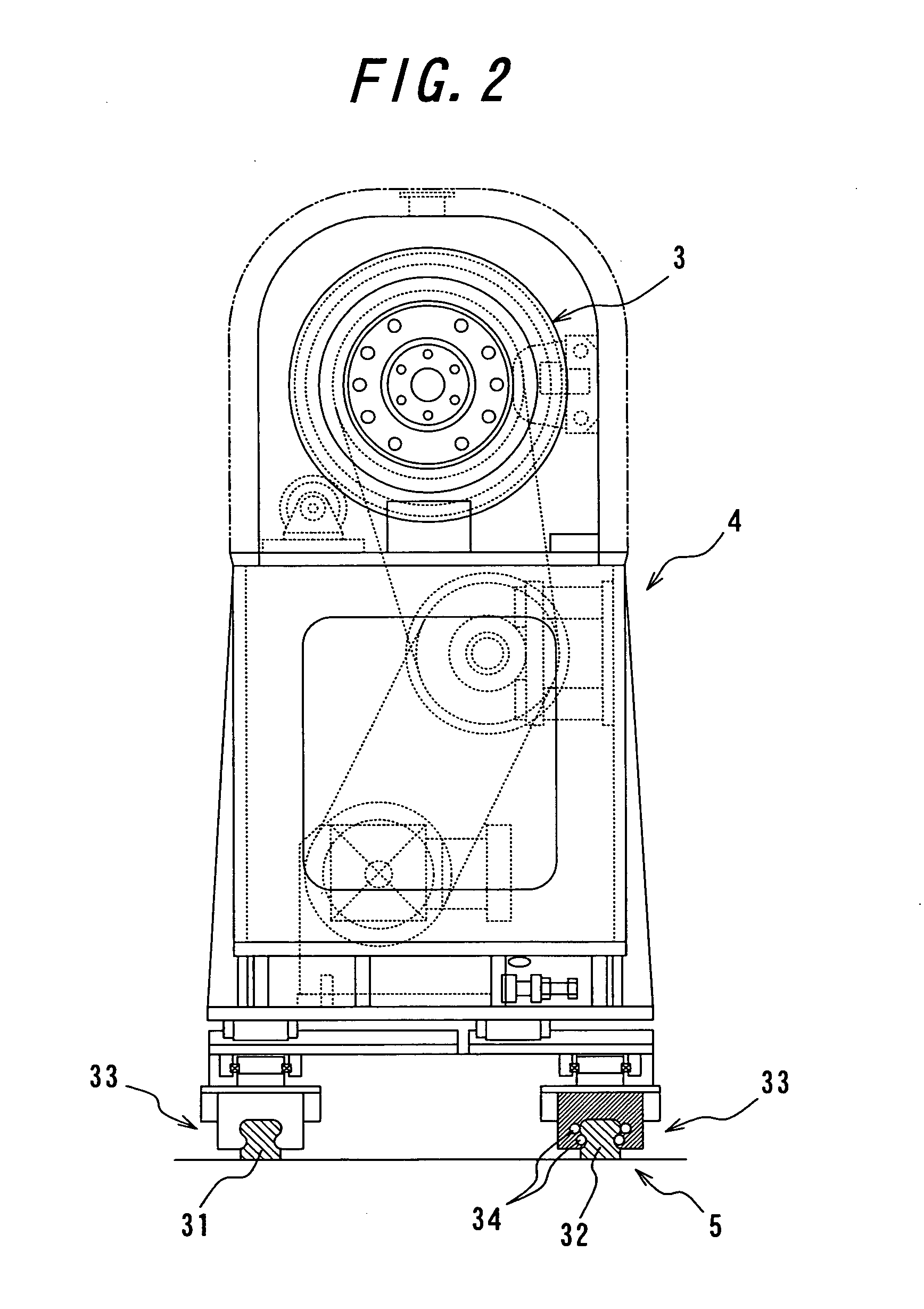
[0035] In this embodiment, the tire building system 1 has a building drum 3, a carriage 4 which positions and places the building drum 3 on it to support the drum in a cantilever manner and which rotates about the center axis of the drum, and an generally ellipse-shaped endless moving path 5 which enables a circular traveling of the carriage 4. The system is also provided with eight workstations F1-F8 for mounting the tire component members on the building drum 3, and the workstations are arranged along the moving path 5.
[0036] Th...
PUM
| Property | Measurement | Unit |
|---|---|---|
| Length | aaaaa | aaaaa |
| Wear resistance | aaaaa | aaaaa |
| Distance | aaaaa | aaaaa |
Abstract
Description
Claims
Application Information