Method of forming bent heat dissipating unit and apparatus therefor

Inactive Publication Date: 2007-08-02
PAN WEN HSING
View PDF1 Cites 6 Cited by
  • Summary
  • Abstract
  • Description
  • Claims
  • Application Information

AI Technical Summary

Benefits of technology

[0006] A primary object of the present invention is to provide a method and apparatus for forming bent heat d

Problems solved by technology

Since the radiating fins 12 must be manually assembled to the curved heat pipe 11 one by

Method used


Image

  • Method of forming bent heat dissipating unit and apparatus therefor
  • Method of forming bent heat dissipating unit and apparatus therefor
  • Method of forming bent heat dissipating unit and apparatus therefor

Examples


Example

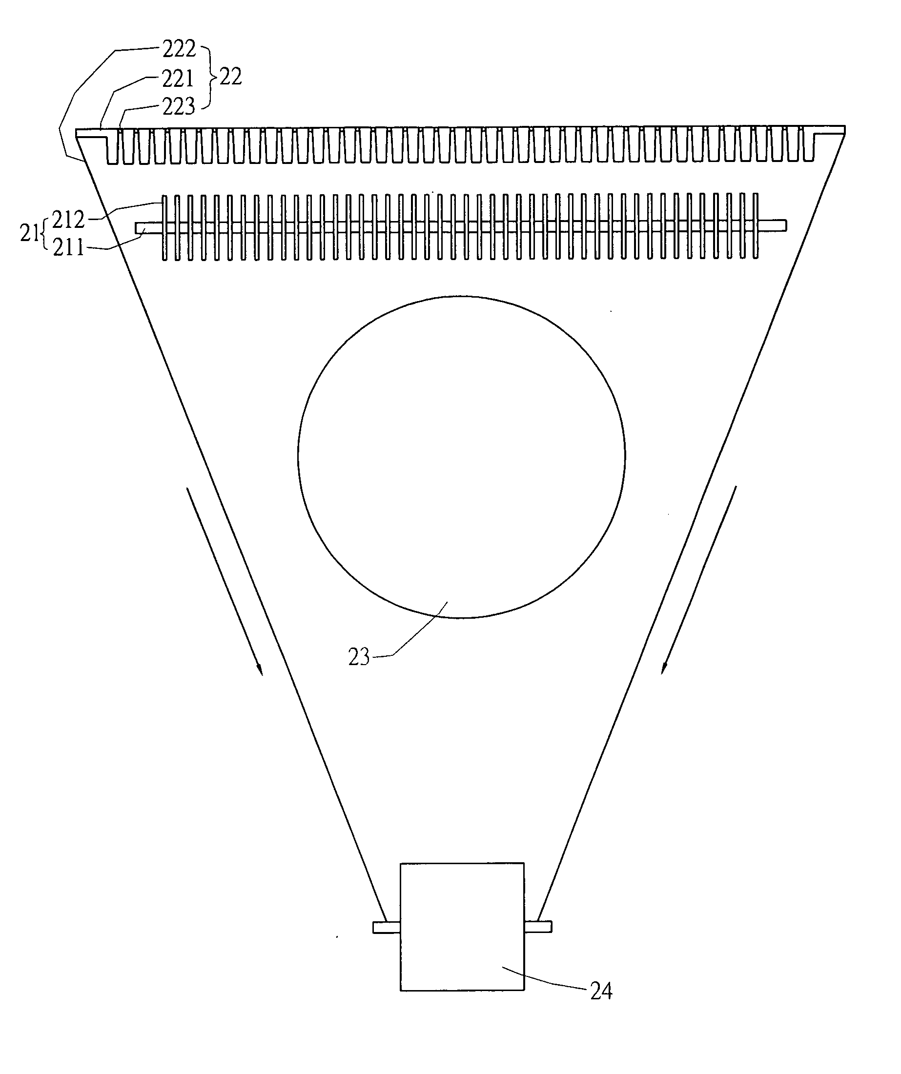
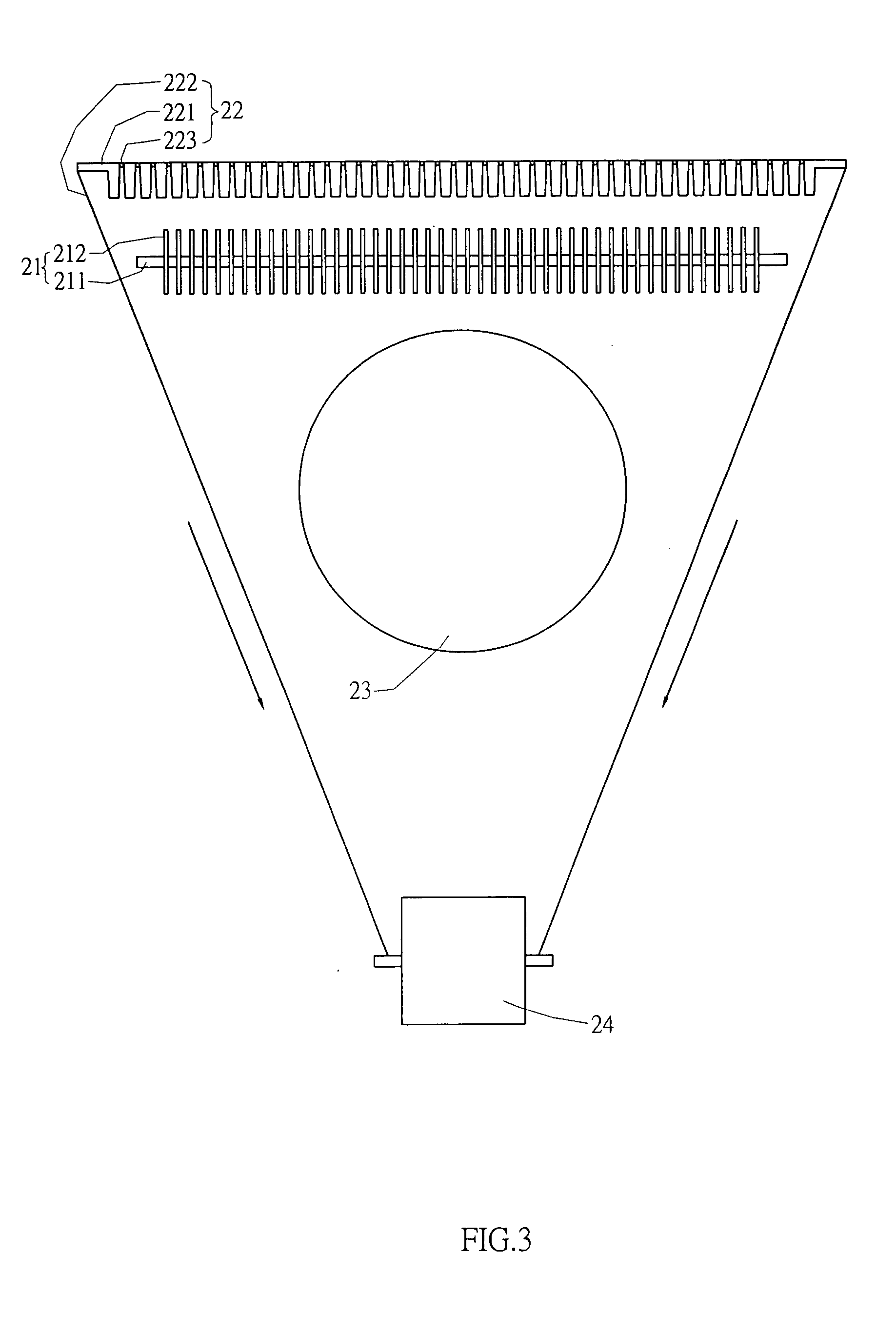
[0019] Please refer to FIGS. 3 and 4 that show the bending of a heat dissipating unit using a method and apparatus according to a preferred embodiment of the present invention. As shown, the apparatus for bending a heat dissipating unit 21 according to the preferred embodiment of the present invention includes a forming die assembly 22, a forming block 23, and a processing machine 24.

[0020] The heat dissipating unit 21 includes a heat pipe 211, which is originally a straight pipe, and a plurality of radiating fins 212 sequentially put on and around the straight heat pipe 211.

[0021] The forming die assembly 22 includes a plurality of locating die units 221 and a carrier 222. The locating die units 221 are sequentially connected to one another using the carrier 222, so that the locating die units 221 are arranged side by side on the carrier 222. It is noted any two adjacent locating die units 221 on the carrier 222 are pivotally connected at an end to each other via a pivot 223, so ...


PUM

PropertyMeasurementUnit
Heataaaaaaaaaa

Abstract

In a method of forming bent heat dissipating unit, the following steps are included: putting a plurality of radiating fins on and around a straight heat pipe to form a heat dissipating unit; engaging the heat dissipating unit with a forming die assembly, so that a plurality of locating die units sequentially arranged on a carrier of the assembly are separately positioned in a space between two adjacent radiating fins; pressing the engaged heat dissipating unit and forming die assembly against a forming block; and driving a processing machine connected to the carrier of the forming die assembly to change the arrangement of the locating die units and thereby bend the heat dissipating unit to a shape corresponding to a profile of the forming block. An apparatus for forming the bent heat dissipating unit through the above steps is also provided.

Description

FIELD OF THE INVENTION [0001] The present invention relates to a method and apparatus for forming bent heat dissipating unit for use on a computer and / or communication related product, and more particularly to a method and apparatus for forming a bent heat pipe with a plurality of radiating fins equally space thereon in an easy and economical manner. BACKGROUND OF THE INVENTION [0002] To enable efficient and effective dissipation of heat transmitted to a heat pipe forming a radiating device, the heat pipe is conventionally divided into three portions, namely, a heat dissipating end, a heat transmitting section, and a heat source connecting end. Normally, the heat pipe is subjected to particular machining to form these three portions. The heat source connecting end is connected to a heat source, so that heat is transmitted from the heat source via the heat source connecting end to the heat transmitting section and the heat dissipating end, at where heat is dissipated using a cooling ...

Claims


Application Information

Patent Timeline
IPC IPC(8): B21D53/02
CPCB21D53/085F28D15/00Y10T29/4935F28F1/24F28D15/02F28F2013/001
Inventor PAN, WEN-HSING
Owner PAN WEN HSING
Why Eureka
Try Eureka