
Walking assist device

Active Publication Date: 2010-08-12
HONDA MOTOR CO LTD
View PDF9 Cites 7 Cited by
  • Summary
  • Abstract
  • Description
  • Claims
  • Application Information

AI Technical Summary

Benefits of technology

[0008]The present invention has been accomplished by improving conventional arts in view of the aforementioned problems, and it is therefore an object of the present invention to provide a walking assist device capable of relieving a burden from a user by disposing an electric component in the walking assist device.
[0011]Since the walking assist device is compactly designed, it is not easy to provide a space to dispose the electric component. However, according to the first aspect of the present invention, by making good use of the long link member constituting the leg link as a disposing space for the electric component, the electric component can be reasonably disposed in the walking assist device without degrading the compactness thereof. Consequently, the burden to the user can be relieved.
[0012]According to the first aspect of the present invention, the link member housing the electric component is formed into a cylindrical shape and the electric component is disposed inside the cylindrical link member, the protection of the electric component against mechanical damage, dust and water can be achieved without the need of providing extra covering members. Moreover, even the built-in electric component generates heat when electrified, since the cylindrical link member is long and has a relatively greater heat capacity, the heat generated by the electric component can be transferred to the cylindrical link member through the heat transfer member and absorbed by the cylindrical link member. Accordingly, there is no need to provide a special cooling device for the electric component, which contributes to the compactness of the walking assist device.
[0013]Further, if the cylindrical link member is made of dielectric material, the built-in electric component can be protected against external electromagnetic waves, and as a result thereof, malfunctions due to incoming noises can be prevented.
[0014]Furthermore, in the first aspect of the present invention, the load transmit portion is composed of a seat member where the user sits astride, the leg link is positioned inward a leg of the user in a lateral direction of the leg, and it is desirable to thermally connect the heat transfer member to a side plate disposed inward the cylindrical link member in a lateral direction of the cylindrical link member. According thereto, the temperature of the side plate at the outer side of the cylindrical link member, facing the leg of the user in the lateral direction, will not become too high even though the heat generated by the electric component is absorbed by the cylindrical link member. Thus, the user will not feel uncomfortable by the heat applied to the leg thereof.
[0015]According to the second aspect of the present invention, by making good use of the seat member as a disposing space for the electric component, the electric component can be reasonably disposed in the walking assist device without degrading the compactness thereof. Consequently, the burden to the user can be relieved. Further, even though the electric component generates heat when electrified, the heat generated by the electric member can be released through the cylindrical link member. Accordingly, there is no need to provide a special cooling device for the electric component, which contributes to the compactness of the walking assist device. Furthermore, since the heat transfer member is disposed at a surface of the seat member opposite to the other surface thereof contacted by the user, the user can be prevented from being subjected to the heat released from the heat transfer member.

Problems solved by technology

Since the walking assist device is compactly designed, it is not easy to provide a space to dispose the electric component.

Method used


Image

  • Walking assist device
  • Walking assist device
  • Walking assist device

Examples


Embodiment Construction

[0021]A walking assist device according to an embodiment of the present invention will be described hereinafter.

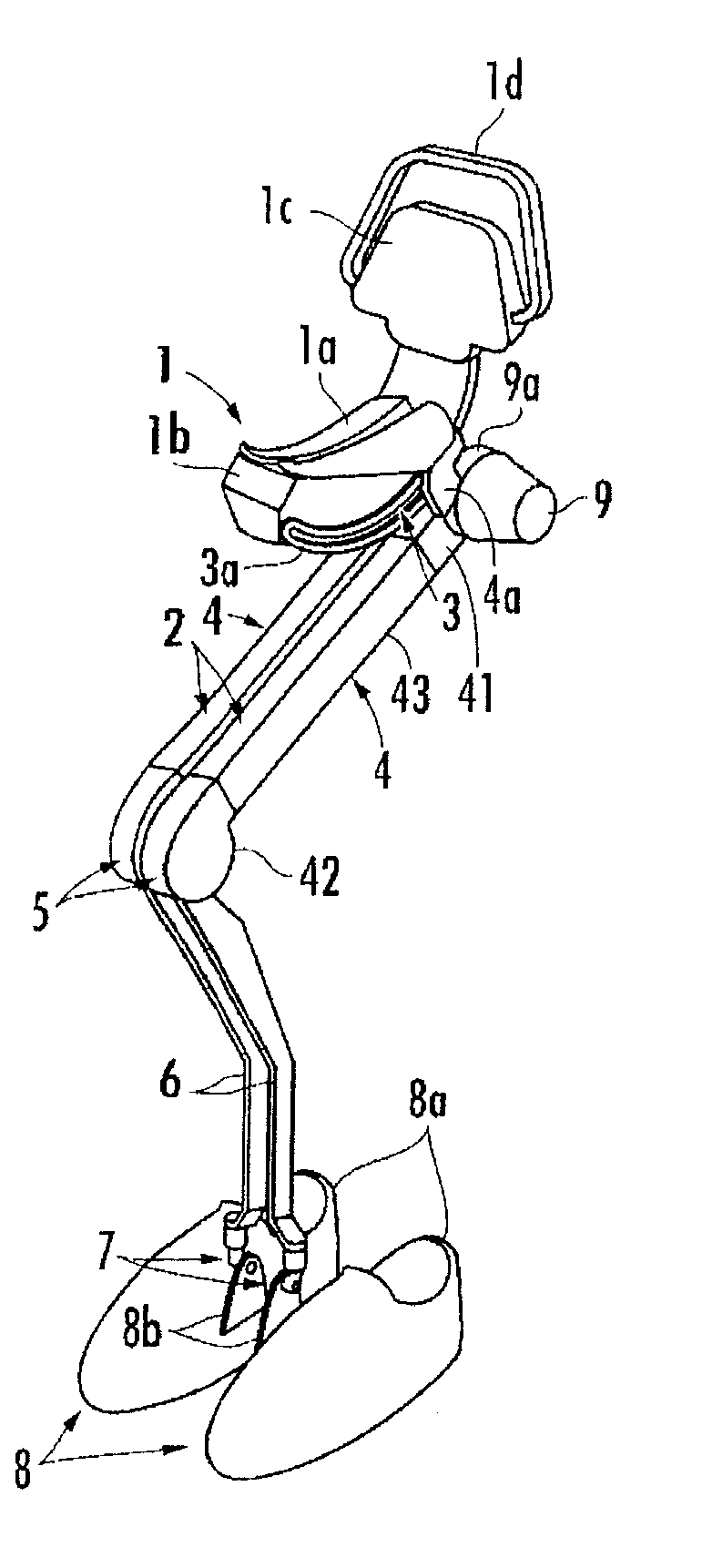
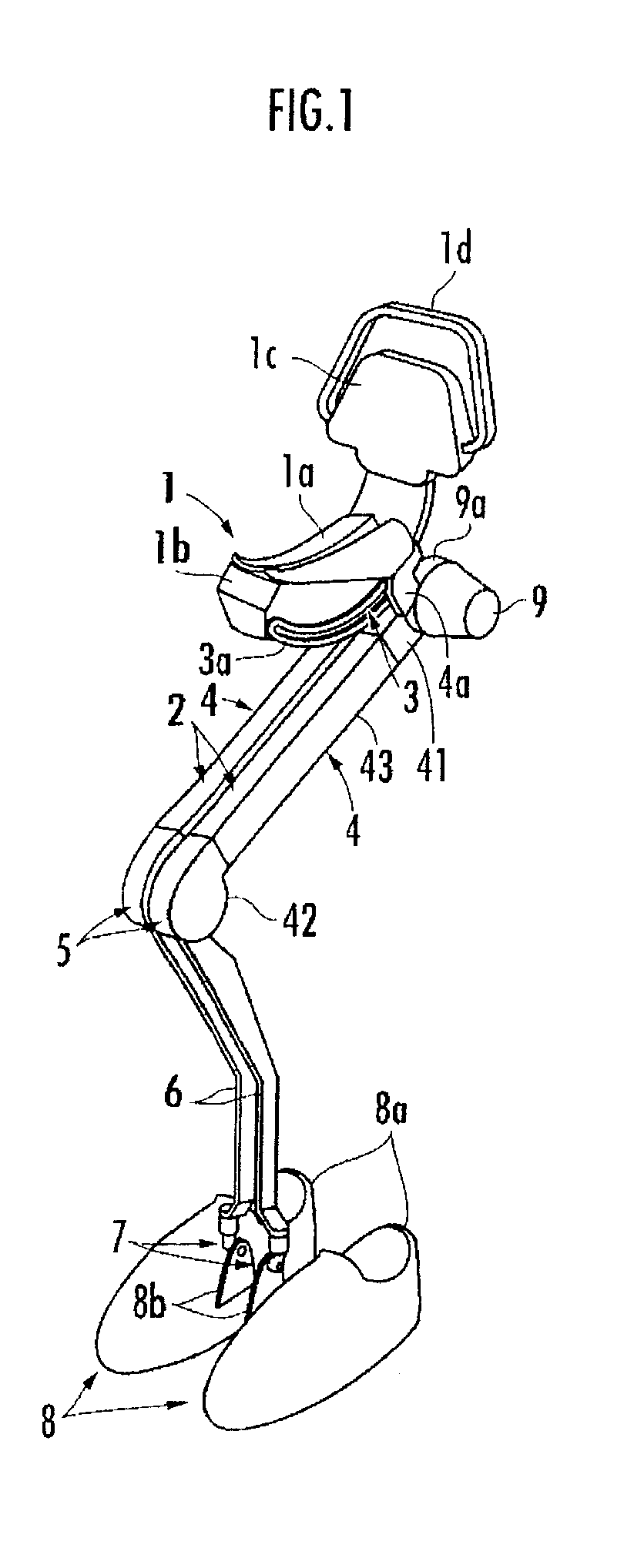
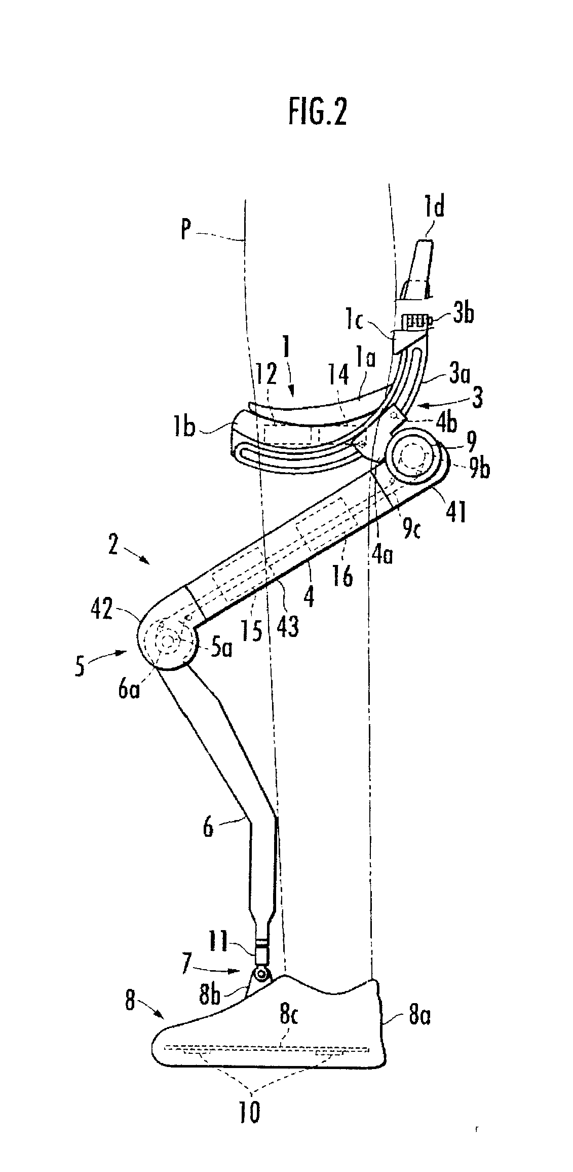
[0022]As illustrated in FIG. 1 through FIG. 3, the walking assist device is provided with a seat member 1 which is equivalent to a load transmit portion where a user P sits astride, a pair of left and right leg links 2 and 2 connected to the seat member 1.

[0023]Each leg link 2 is a freely stretchable and bendable link composed of a first link 4 connected to the seat member 1 through a first joint portion 3 at the upper end portion of the first link 4 and a second link 6 connected to the lower end portion of the first link 4 through a rotary second joint portion 5. The lower end portion of the second link 6 is connected through a third joint portion 7 to a foot installation portion 8 to be mounted by each foot of the user P.

[0024]Each leg link 2 is further mounted with a driving source 9 for driving the second joint portion 5. When the second joint portion 5 is driven by th...


PUM


Abstract

A walking assist device having a load transmit portion, a leg link connected to the load transmit portion, and a driving source capable of driving the leg link in a direction to raise a seat member, so that at least a partial weight of a user may be supported by the leg link through the load transmit portion. An electric component to be used for controlling the driving source can be mounted on the walking assist device without degrading the compactness of the walking assist device. At least a part of the leg link is constituted of a cylindrical link member in which at least the electric component, such as a motor driver to be used for the control of the driving source, is partially housed. The walking assist device also includes a heat transfer member for absorbing the heat of the electric component by the cylindrical link member. The heat transfer member is thermally connected to a side plate of the cylindrical link member directed toward the side opposite to the leg of the user.

Description

PRIORITY CLAIM[0001]The present application is based on and claims the priority benefit of Japanese Patent Application 2007-202996 filed on Aug. 3, 2007, the contents of which are incorporated herein by reference in its entirety.BACKGROUND OF THE INVENTION[0002]1. Field of the Invention[0003]The present invention relates to a walking assist device which assists a user in walking by relieving a load applied to a leg thereof.[0004]2. Description of the Related Art[0005]Conventionally, there has been known a walking assist device having a seat member, a leg link connected to the load transmit portion and provided with at least one joint portion and a driving source for driving the joint portion provided in the leg link (for example, refer to Japanese Patent Laid-open No. 2007-20909). The driving source in this type of walking assist device drives the leg link in the direction of pushing up the seat member; therefore, at least a partial weight of a user is supported by the seat member t...

Claims


Application Information

Patent Timeline
IPC IPC(8): A61H1/00
CPCA61H3/008A61H2201/0214A61H2201/1633A61H2201/5007A61H2201/5061A61H2201/5071A61H2201/1676A61H2201/1215A61H2201/1623A61H2201/1635A61H2201/1642A61H2201/165A61H3/00
Inventor ASHIHARA, JUNIKEUCHI, YASUSHIKUDOH, HIROSHIHIKI, YUTAKANODA, TATSUYAKOSHIISHI, TAKESHI
Owner HONDA MOTOR CO LTD
Learn More