
Valve structure of shock absorber

Active Publication Date: 2018-11-29
HL MANDO CORP
View PDF7 Cites 4 Cited by
  • Summary
  • Abstract
  • Description
  • Claims
  • Application Information

AI Technical Summary

Benefits of technology

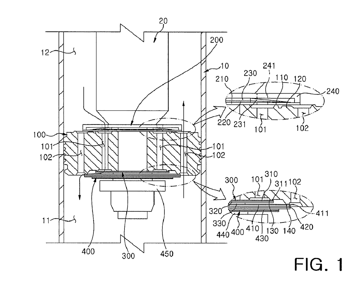
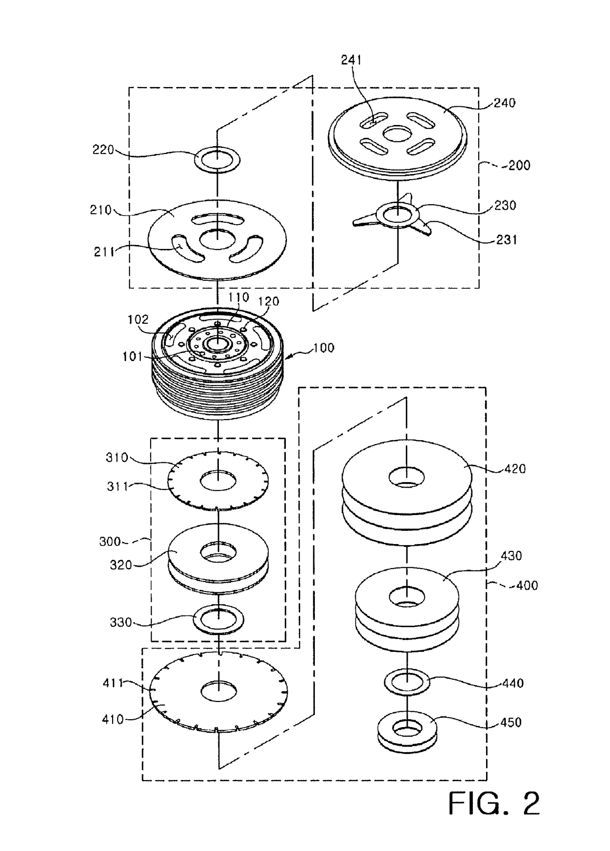
The present invention provides a way to reduce costs and weight by omitting a retainer for supporting a disc valve and by using a side surface of a piston to form channels. This makes it easier to secure space. Additionally, the invention prevents deformation and damage to the intake disc, which improves the durability of the apparatus.

Problems solved by technology

However, in an existing conventional piston valve, a retainer for supporting a disc valve is additionally coupled to an upper or lower portion of a piston, and thus, the number of components is increased to increase the manufacturing costs and weight thereof.
In addition, since a channel should be formed within a diameter of the retainer, it is difficult to secure a space for forming the channel.

Method used


Image

  • Valve structure of shock absorber
  • Valve structure of shock absorber
  • Valve structure of shock absorber

Examples


Embodiment Construction

[0024]Hereinafter, exemplary embodiments according to the present invention will be described in detail with reference to the accompanying drawings.

[0025]The advantages, features, and schemes of achieving the advantages and features of the present exemplary embodiments will be made apparent to and comprehended by those skilled in the art based on the exemplary embodiments, which will be described later in detail, together with accompanying drawings.

[0026]The present exemplary embodiments are not limited to the following exemplary embodiments but include various applications and modifications. The present exemplary embodiments will make the disclosure of the present invention complete, and allow those skilled in the art to completely comprehend the scope of the present invention. The present exemplary embodiments are only defined within the scope of accompanying claims.

[0027]In addition, details of generally known technology that make the subject matter of the present exemplary embod...


PUM


Abstract

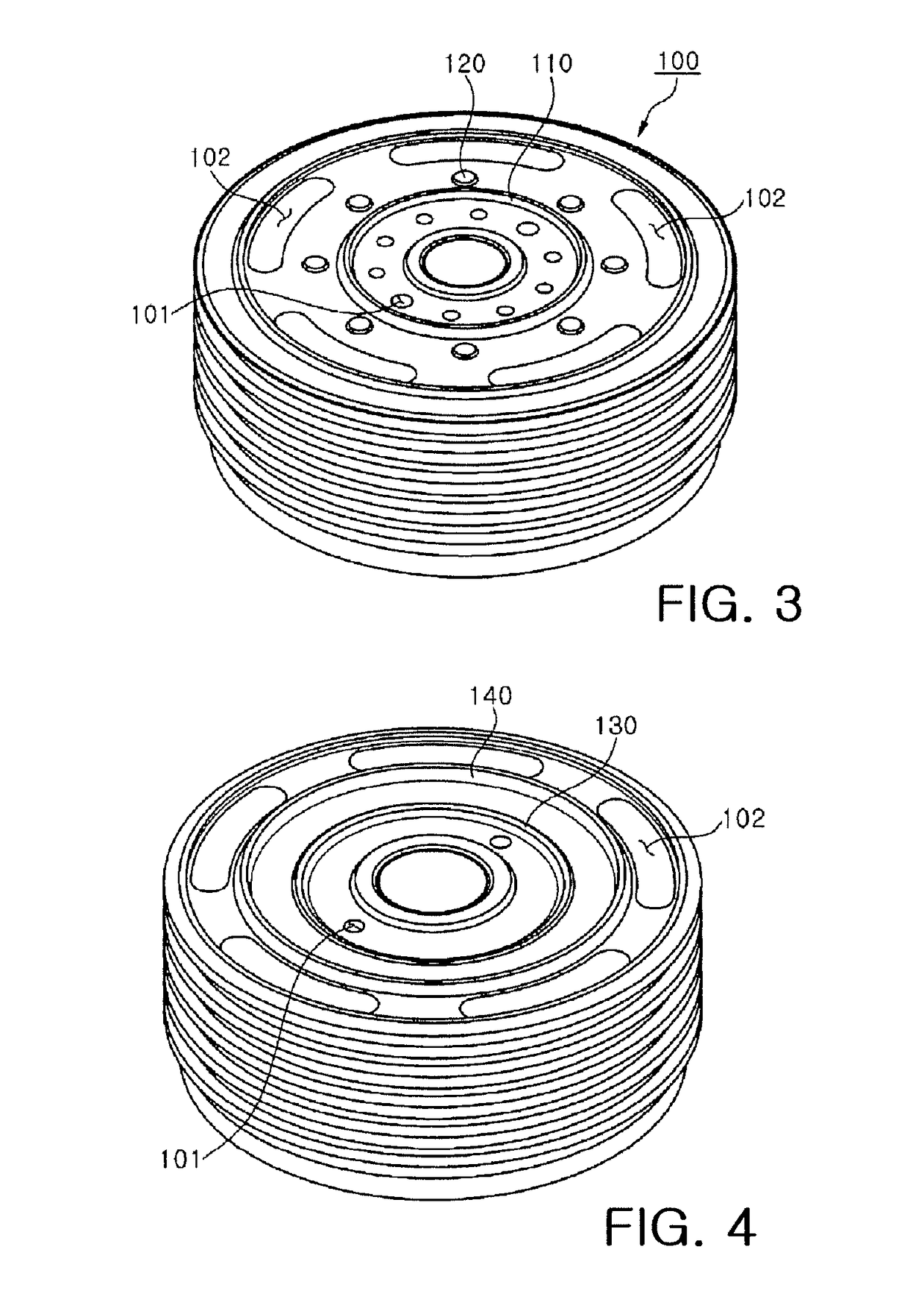
The present invention relates to a valve structure of a shock absorber, in which a rebound-side stepped portion for supporting a rebound-side disc valve is integrally molded with an upper surface of a piston, and a compression-side inner stepped portion and a compression-side outer stepped portion for supporting a compression-side disc valve are integrally molded with a lower surface of the piston to omit a retainer for supporting a disc valve, thereby simplifying a structure and reducing manufacturing costs and weight of the valve structure, and a side surface of the piston is used to form compression channels, thereby easily securing a space.

Description

TECHNICAL FIELD[0001]The present invention relates to a valve structure of a shock absorber, and more particularly, to a valve structure of a shock absorber, in which a retainer for supporting a disc valve is omitted by integrally molding stepped portions for supporting a valve disc with upper and lower surfaces of a piston, thereby simplifying a structure and reducing manufacturing costs and weight of the valve structure, and in which compression channels are formed by using a side surface of the piston, thereby easily securing a space.BACKGROUND ART[0002]Generally, a shock absorber prevents vibration from being directly transferred to a vehicle body by absorbing and buffering vertical vibration energy transferred to vehicle wheels from an uneven road surface.[0003]The shock absorber includes a cylinder filled with a working fluid such as oil, a piston valve movably installed in the cylinder and portioning the cylinder into a compression chamber and a rebound chamber, a piston rod ...

Claims


Application Information

Patent Timeline
IPC IPC(8): F16F9/348F16F9/512F16K31/122
CPCF16F9/348F16F9/5126F16K31/1226F16F2230/0023F16F2228/066F16F9/34F16K3/04F16K3/314F16F9/3485B60G13/06F16F9/3405
Inventor CHEONG, MOON SANG
Owner HL MANDO CORP
Learn More