Transducer motor structure and inside-only voice coil for use in loudspeakers

Active Publication Date: 2010-06-17
ONEILL ROBERT M
View PDF3 Cites 12 Cited by
  • Summary
  • Abstract
  • Description
  • Claims
  • Application Information

AI Technical Summary

Benefits of technology

[0051]A part of the diaphragm known as the “dust cap” is attached to the diaphragm above the pole piece but this part is easily spaced away from the top of the pole piece to allow sufficient clearance for maximum required displacement.
[0052]In conventional designs, it is a common practice to make the gap between the inside diameter of the bobbin and the outside diameter of the pole tip (for pot core designs) or the pole piece (for pancake designs) smaller than that gap between the outside diameter of the voice coil and the inside diameter of the pot core (for pot core designs) or the front plate (for pancake designs). This is done to allow the voice coil assembly to expand physically as it heats. This conventional method requires more space on the outside of the coil so that as the voice coil assembly increases in diameter, it will not come into contact with the inside diameter of the pot core or front plate.
[0053]If the voice coil wire touches the pot core or front plate it will produce an audible rub, or distortion, and frequently will produce a catastrophic failure of the loudspeaker by producing an electrical short circuit or open circuit.
[0054]The conventional design geometry allows the voice coil to expand toward the pot core or front plate, and so as the prior art voice coil becomes hotter, it expands toward possible contact with the front plate.
[0055]In the preferred embodiment of the motor structure, the front plate has a selected thickness and vertical extent for its inner peripheral sidewall, facing the magnetic gap, and, ignoring the fringe effects of the magn

Problems solved by technology

In particular, high power signals drive a speaker's diaphragm or cone into extreme excursions and can cause the (usually pistonic) motion of the diaphragm to become mis-aligned when driven by more challenging audio signals.
Narrow and efficient magnetic gaps create other problems, however, because the close mechanical tolerances of a tight magnetic gap require the outer winding surfaces of voice coil 102 to reciprocate in and out in very close proximity to the inner edge of top plate 105.
Loudspeaker or woofer failure can be often attributed to these types of thermal or mechanical overloading problems.
Substantial amounts of power are required to provide competition-winning sound pressure levels, and signals having such power require very large current flow through voice coil conductors, thus generating substantial amounts of heat and driving the woofer's diaphragm to extreme excursions.
Those extreme excursions generate extreme mechanical loads on the diaphragm and its supportive suspension.
In competitions, operators seek the loudest possible playback and often over-drive the loudspeaker drivers, causing voice coils to burn out or open circuit.
These heat levels are extreme and can produce device failure due to degradation of the adhesive systems used to bond the voice coil to its carrier as well as the adhesives used to bond

Method used


Image

  • Transducer motor structure and inside-only voice coil for use in loudspeakers
  • Transducer motor structure and inside-only voice coil for use in loudspeakers
  • Transducer motor structure and inside-only voice coil for use in loudspeakers

Examples


Example

[0078]Before explaining exemplary embodiments and methods of the present invention in detail, it is to be understood that the invention is not limited in its application to the details of construction and to the arrangements of the components set forth in the following description or illustrated in FIGS. 11-16B. The invention is capable of other embodiments and of being practiced and carried out in various ways. Also, it is to be understood that the phraseology and terminology employed herein are for the purpose of description and should not be regarded as limiting.

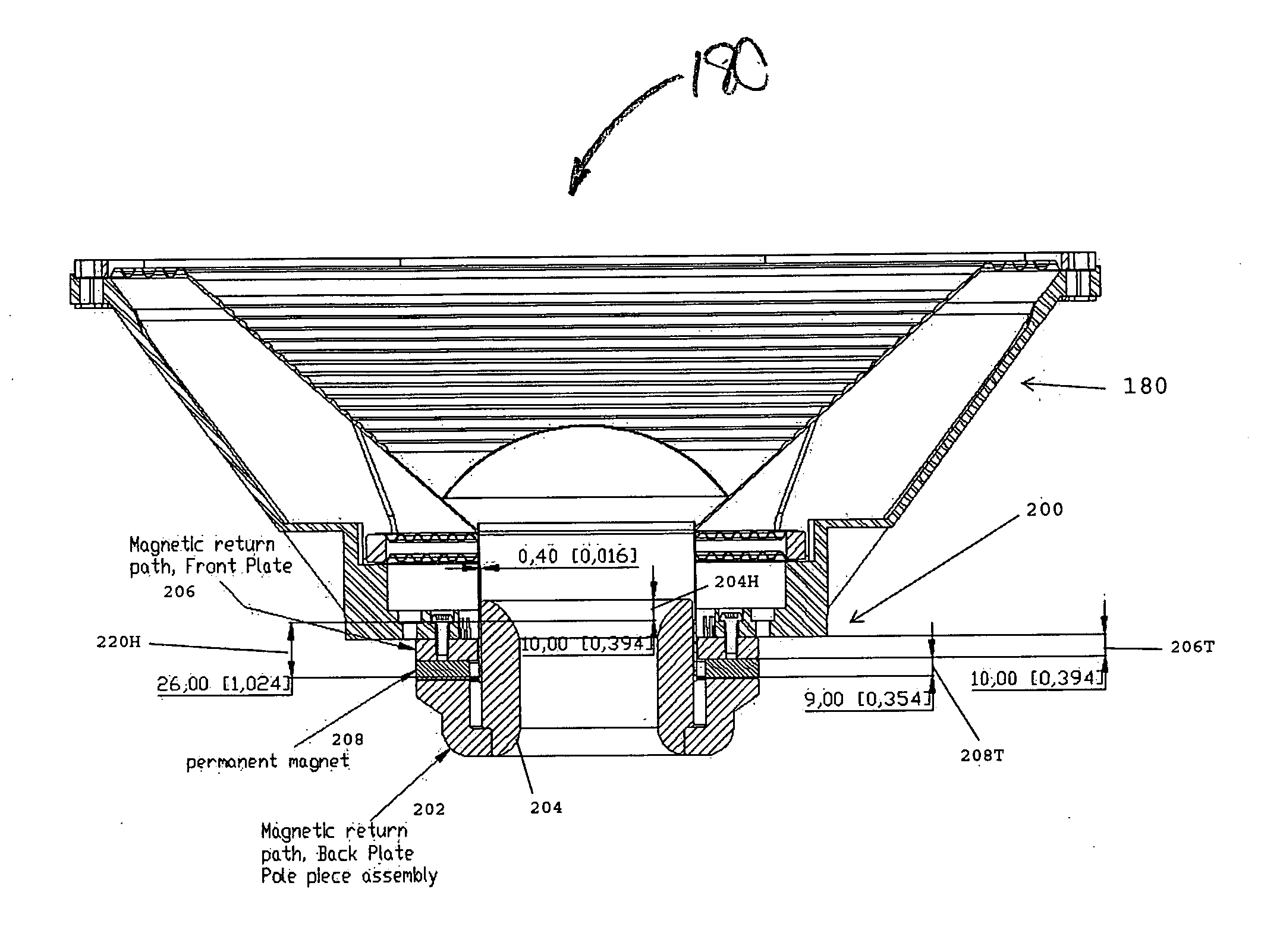
[0079]Turning now to FIGS. 11-16B, in accordance with the method and structure of the present invention, a new loudspeaker 180 has a motor structure 200 including an electrically conductive voice coil 220 made of conductor wound solely and entirely within a (preferably) cylindrical bobbin or former 210 to provide a voice coil assembly having a smooth, tough resilient cylindrical exterior sidewall surface that is ideally w...


PUM

PropertyMeasurementUnit
Lengthaaaaaaaaaa
Thicknessaaaaaaaaaa
Volumeaaaaaaaaaa

Abstract

An electromechanical transducer 180, motor structure 200 and voice coil winding support structure or bobbin 210 are configured to protect and transport heat away from a voice coil 220 which is would solely within the interior of bobbin 210 and configured for reciprocating movement in close proximity to an extended cooling pole piece 204. A compact, economical and efficient adaptation of a pancake style motor includes generous volume for a powerful magnet 208, while providing an extended, linear range of excursion and continuous cooling for the generously overhung voice coil 220.

Description

PRIORITY CLAIMS AND REFERENCE TO RELATED APPLICATIONS[0001]This application claims priority to related, commonly owned U.S. provisional patent application No. 60 / 905,844, filed Mar. 9, 2007, the entire disclosure of which is incorporated herein by reference.BACKGROUND OF THE INVENTION[0002]1. Technical Field of the Invention[0003]The present invention relates to electromechanical transducers and motor structures, and, more particularly, to loudspeaker driver voice coil winding support structures and methods for configuring voice coils for use in loudspeaker applications.[0004]2. Description of the Background Art[0005]Recent market emphasis on long excursion, high power dissipation loudspeakers (e.g., low frequency drivers or woofers) has challenged manufacturers to make products which will withstand previously unimaginable levels of abuse. DB drag races and other forms of loudness-level competition have created markets for amplifiers and loudspeakers dissipating several kilowatts (k...

Claims


Application Information

Patent Timeline
IPC IPC(8): H04R1/02
CPCH04R9/022Y10T29/49071Y10T29/49007Y10T29/49005Y10T29/49073
Inventor O'NEILL, ROBERT M.
Owner ONEILL ROBERT M
Why Eureka
Try Eureka