System and method for detecting a leak in a hydraulic fluid system

a hydraulic fluid and system technology, applied in the direction of fluid-tightness measurement, instrumentation, measurement of fluid loss/gain rate, etc., can solve the problems of excessive fluid loss, fluid loss, hydraulic fluid leakage,

Active Publication Date: 2007-02-08
THE BOEING CO
View PDF10 Cites 30 Cited by
  • Summary
  • Abstract
  • Description
  • Claims
  • Application Information

AI Technical Summary

Benefits of technology

[0005] In accordance with methods consistent with the present invention, a method for operating a hydraulic system in an aircraft is provided. The hydraulic system includes a reservoir, a conduit operatively connected to the reservoir, and fluid. The method comprises: setting a leak detection level to a value

Problems solved by technology

Vehicles (such as aircraft or automobiles) and machines (such as cranes or presses) using hydraulic systems to move or control objects often experience hydraulic fluid leaks in the lines, pumps, or actuators typically included in the hydraulic system.
By using fixed fault reaction levels, conventional leak detection systems often allow excessive fluid to be lost before the system determines a fault r

Method used


Image

  • System and method for detecting a leak in a hydraulic fluid system
  • System and method for detecting a leak in a hydraulic fluid system
  • System and method for detecting a leak in a hydraulic fluid system

Examples


Embodiment Construction

[0016] Reference will now be made in detail to an implementation in accordance with methods, systems, and products consistent with the present invention as illustrated in the accompanying drawings. The same reference numbers may be used throughout the drawings and the following description to refer to the same or like parts.

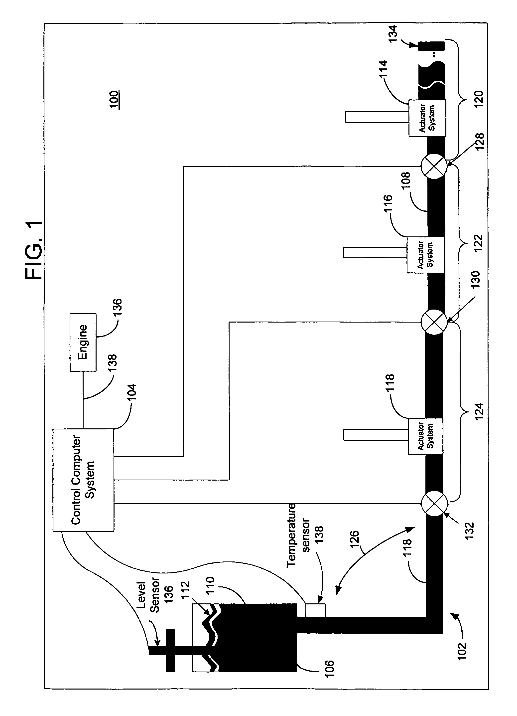
[0017]FIG. 1 depicts a block diagram of an exemplary system 100 employing a hydraulic fluid system 102 and having a computer control system 104 suitable for detecting a leak in the hydraulic fluid system 102 consistent with the present invention. The system 100 may be a vehicle or machine (such as an aircraft, automobile, ship, crane, or press) that employs the hydraulic fluid system 102 to move or control an object or surface (not shown in the figures). The hydraulic fluid system 102 includes a reservoir 106, a conduit 108 operatively connected to the reservoir 106, and a hydraulic fluid 110 disposed within the reservoir 106 and the conduit 108 such that the fl...


PUM


Abstract

Methods, systems, and articles of manufacture consistent with the present invention provide for detecting a leak in a hydraulic fluid system having a reservoir and a conduit operatively connected to the reservoir. The fluid may reside in the reservoir, the conduit, or both. A current level of the fluid in the reservoir is sensed. A determination is made as to whether the current level is less than a leak detection level. When it is determined that the current level is greater than the leak detection level, a current temperature of the fluid is sensed and the leak detection level is updated based on the current temperature of the fluid so that thermal expansion of the fluid in the system is considered in detecting and isolating a leak.

Description

BACKGROUND OF THE INVENTION [0001] The present invention relates to systems for hydraulic leak detection, and, more particularly, to systems and methods for detecting a leak in a hydraulic fluid system by calculating a leak detection level of a reservoir based on a current temperature of the hydraulic fluid during operation of the system. [0002] Vehicles (such as aircraft or automobiles) and machines (such as cranes or presses) using hydraulic systems to move or control objects often experience hydraulic fluid leaks in the lines, pumps, or actuators typically included in the hydraulic system. Conventional leak detection systems typically use fixed hydraulic reservoir levels as fault reaction levels to determine whether a leak has occurred and to isolate the leak. These fixed fault reaction levels are constant hard coded values in software used by the leak detection system. By using fixed fault reaction levels, conventional leak detection systems often allow excessive fluid to be los...

Claims


Application Information

Patent Timeline
IPC IPC(8): G01M3/28G01M99/00
CPCF15B1/02G01M3/26F15B2201/50F15B19/005
Inventor BEIDERMAN, ALLAN R.REXING, PATRICK J.
Owner THE BOEING CO
Why Eureka
Try Eureka