Under vehicle inspection system

a vehicle inspection and vehicle technology, applied in closed circuit television systems, television systems, color television details, etc., can solve the problems of inconvenient detection of suspicious objects, inconvenient detection, and inability to detect suspicious objects, so as to minimize the risk of physical harm, the effect of detecting suspicious objects reliably and efficiently

Inactive Publication Date: 2007-02-08
RILEY LARRY
View PDF17 Cites 37 Cited by
  • Summary
  • Abstract
  • Description
  • Claims
  • Application Information

AI Technical Summary

Benefits of technology

[0018] Embodiments of the invention provide an under vehicle inspection system capable of reliably and efficiently detecting suspicious articles in the undercarriages of vehicles while minimizing the risk of physical harm to inspection personnel. In o

Problems solved by technology

Most notably, this approach puts the inspector in physical danger by placing him or her near potentially harmful substances, e.g. explosives, caustic chemicals, biological weapons, etc.
Furthermore, scanning the entire underside of a vehicle using a mirror on a stick takes a considerable amount of time, which typically leads to serious congestion in high traffic areas.
Moreover, human inspectors often fail to notice important details when they are fatigued or in a rush, thereby limiting the reliability of their inspections.
Stationary under vehicle scanners and UGVs each have some major problems.
Stationary under vehicle scanners generally produce very poor quality (e.g., blurry) images due to the fact that the vehicles driven over these devices often travel at inconsistent speeds and impart significant mechanical vibration to the imaging device as they pass over the scanning point.
Furthermore, cameras fixed in stationary under vehicle scanners are generally incapable of selectively focusing in on suspicious areas of the undercarriage or adjusting their imaging view around a difficult angle.
As such, stationary under vehicle scanners are unable to inspect areas such as wheel wells, which are a common place for stowing illegal items.
UGVs, on the other hand, experience poor and inconsistent image quality due to frequent image transmission failures caused by the mobile unit losing line of sight with a receiver station or due to radio frequency interference.
In addition, because UGVs have a fixed size, they cannot adapt to the varying heights of vehicle undercarriages, and therefore cannot accommodate the international ground clearance standard of one (1) inch.
Another problem with UGVs is that they have trouble moving around on poor or uneven surfaces

Method used


Image

  • Under vehicle inspection system
  • Under vehicle inspection system
  • Under vehicle inspection system

Examples


Embodiment Construction

[0028] Exemplary embodiments of the invention are described below with reference to the corresponding drawings. These embodiments are presented as teaching examples. The actual scope of the invention is defined by the claims that follow.

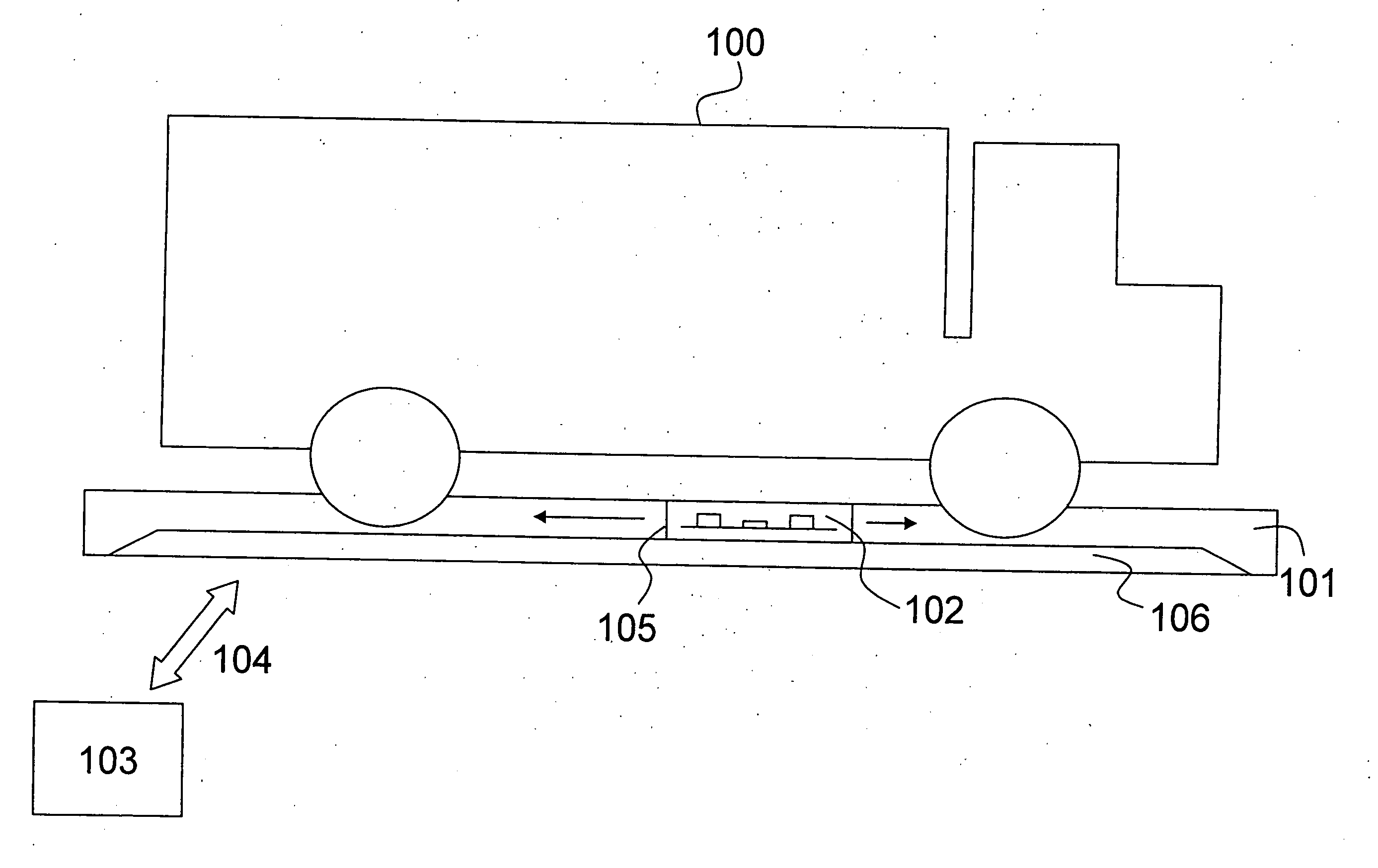
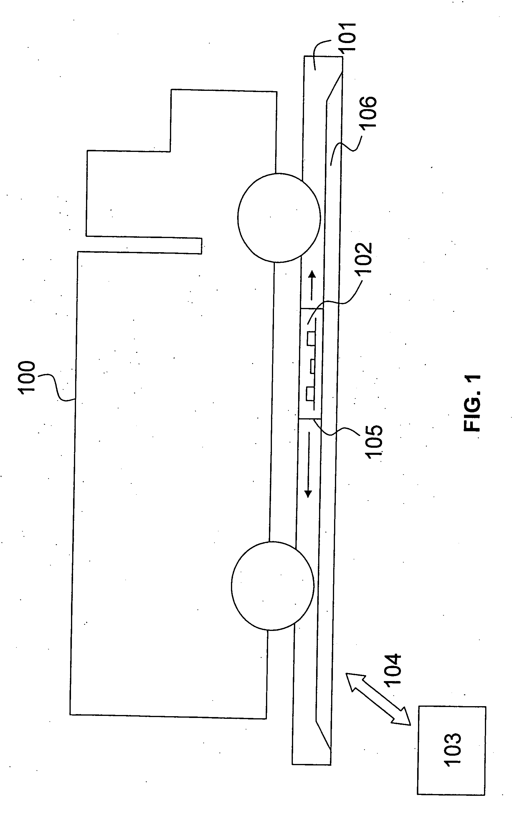
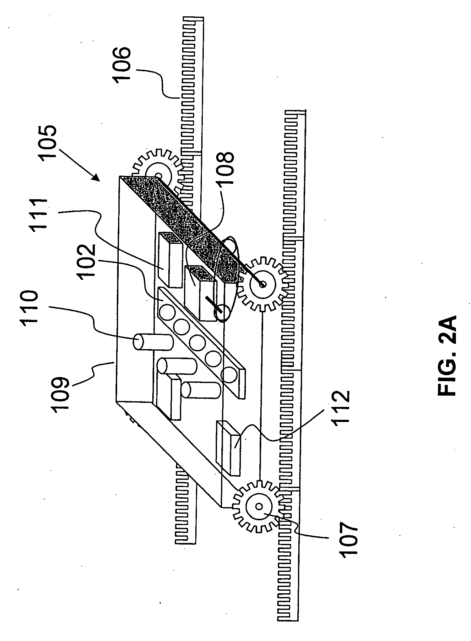
[0029] One embodiment of the present invention provides an under vehicle inspection system comprising a vehicle undercarriage inspection platform and a plurality of sensors mounted on the vehicle undercarriage inspection platform. The plurality of sensors is adapted to scan all or part of the vehicle undercarriage by moving relative to the vehicle undercarriage inspection platform. Data captured by the plurality of sensors is communicated to an analysis element and evaluated.

[0030] The term “platform” is used throughout this description to denote any physical structure capable of receiving and / or supporting a vehicle, in whole or in part, in such a manner that a plurality of sensors associated with the platform may view a significant portion of the...


PUM


Abstract

An under vehicle inspection system is disclosed. The under vehicle inspection system comprises a vehicle undercarriage inspection platform, a sensor mounted on sensor carriage, and a data analysis element receiving and evaluating data obtained by the sensor.

Description

CROSS REFERENCE TO RELATED APPLICATIONS [0001] This application is a continuation-in-part of U.S. patent application Ser. No. 11 / 045,074 filed on Jan. 31, 2005, the disclosure of which is hereby incorporated by reference in its entirety.STATEMENT OF GOVERNMENT SPONSORED RESEARCH [0002] One or more agencies of the United States Government have a paid-up license in this invention and may in limited circumstances possess the right to require the patent owner to license others on reasonable terms as provided by the terms of Government Contract Number N00164-04-C-6653 awarded by the Naval Surface Warfare Center, Crane Ind.BACKGROUND OF THE INVENTION [0003] 1. Field of the Invention [0004] Embodiments of the invention relate generally to an under vehicle inspection system. More particularly, embodiments of the invention relate to an under vehicle inspection system and related method of vehicle inspection. [0005] 2. Description of the Related Art [0006] Criminals and terrorists have been k...

Claims


Application Information

Patent Timeline
IPC IPC(8): H04N7/18
CPCH04N7/181
Inventor RILEY, LARRY
Owner RILEY LARRY
Why Eureka
Try Eureka