Under vehicle inspection system

a vehicle inspection and vehicle technology, applied in the field of vehicle inspection systems, can solve the problems of inconvenient detection of suspicious objects, so as to minimize the risk of physical harm, reliable and efficient detection of suspicious objects

Inactive Publication Date: 2007-02-22
RILEY LARRY E
View PDF10 Cites 61 Cited by
  • Summary
  • Abstract
  • Description
  • Claims
  • Application Information

AI Technical Summary

Benefits of technology

[0018] Embodiments of the invention provide an under vehicle inspection system capable of reliably and efficiently detecting suspicious articles in the undercarriages of vehicles while minimizing the risk of physical harm to inspection personnel. In one embodiment of the invention, a full width image of a vehicle's undercarriage is captured in a single scan along the length of the undercarriage. The image is preferably captured using a single camera in a camera carriage moving along a smooth track on a transportable vehicle undercarriage inspection platform.
[0020] According to another embodiment of the invention, an undercarriage inspection platform for an under vehicle inspection system comprises a tongue assembly, a scanning platform, and a wheel / axel assembly. The scanning platform comprises a camera carriage track adapted to support a camera carriage such that the camera carriage can move along the length of a vehicle to perform an under vehicle inspection. The wheel / axel assembly comprises a frame, wheels, and axels and adapted to be connected to the tongue assembly and scanning platform during transportation and detached from the tongue assembly and scanning platform so that the scanning platform can lay on the ground during under vehicle inspections.

Problems solved by technology

Most notably, this approach puts the inspector in physical danger by placing him or her near potentially harmful substances, e.g. explosives, caustic chemicals, biological weapons, etc.
Furthermore, scanning the entire underside of a vehicle using a mirror on a stick takes a considerable amount of time, which typically leads to serious congestion in high traffic areas.
Moreover, human inspectors often fail to notice important details when they are fatigued or in a rush, thereby limiting the reliability of their inspections.
Stationary under vehicle inspection devices and UGVs each have some major problems.
For example, stationary under vehicle inspection devices generally produce very poor quality (e.g., blurry) images due to the fact that the vehicles driven over these devices often travel at inconsistent speeds and impart significant mechanical vibration to the imaging device as they pass over the inspection point.
Furthermore, cameras fixed in stationary under vehicle inspection devices are generally incapable of selectively focusing in on suspicious areas of the undercarriage or adjusting their imaging view around a difficult angle.
As such, conventional stationary under vehicle inspection devices are unable to inspect areas such as wheel wells, which are a common place for stowing illegal items.
UGVs, on the other hand, experience poor and inconsistent image quality due to frequent image transmission failures caused by the mobile unit losing line of sight with a receiver station or due to radio frequency interference, and also due to image blur and jitter resulting from the motion of the UGV In addition, because UGVs have a fixed size, they cannot adapt to the varying heights of vehicle undercarriages, and therefore cannot accommodate the low ground clearance, e.g., of vehicles that are missing their shocks, etc.
Another problem with UGVs is that they have trouble moving around on poor or uneven surfaces such as mud or gravel.
Furthermore, inspections made by UGVs are usually random, as the mobile robot moves around selected areas of the vehicle undercarriage rather than uniformly scanning the entire structure.
Finally, as with stationary under vehicle scanners, UGVs are unable to inspect most wheel wells because their available view angles are often obstructed by vehicle wheels and other vehicle parts.
In addition, some problems that are common to both stationary under vehicle inspection devices and UGVs include a tendency to be adversely affected by environmental conditions such as debris and changing weather, and an inability maintain a precise spatial relationship with a vehicle's undercarriage.
The first problem may occur, for example, where substances such as dirt or mud come in contact with these devices' optical, mechanical, or electrical components, or where the air temperature causes temperature sensitive components such as digital image sensors to perform sub-optimally.
The second problem tends to occur in stationary under vehicle inspection devices due to their inability to precisely track a vehicle's position, e.g., due to the vehicle's inconsistent speed, elevation, etc., and it occurs in UGVs due to their inability to precisely track their own position, e.g., because they may be moving around on uneven or unpredictable surfaces.
The tendency to be adversely affected by environmental conditions increases the maintenance cost and decreases the reliability of these technologies, and the inability to maintain a precise spatial relationship with the vehicle's undercarriage tends to complicate the image capture and analysis process.
Given the great risk that this method presents to inspection personnel, however, the mirror on a stick approach is unacceptable.

Method used


Image

  • Under vehicle inspection system
  • Under vehicle inspection system
  • Under vehicle inspection system

Examples


Embodiment Construction

[0043] Exemplary embodiments of the invention are described below with reference to the corresponding drawings. These embodiments are presented as teaching examples. The actual scope of the invention is defined by the claims that follow.

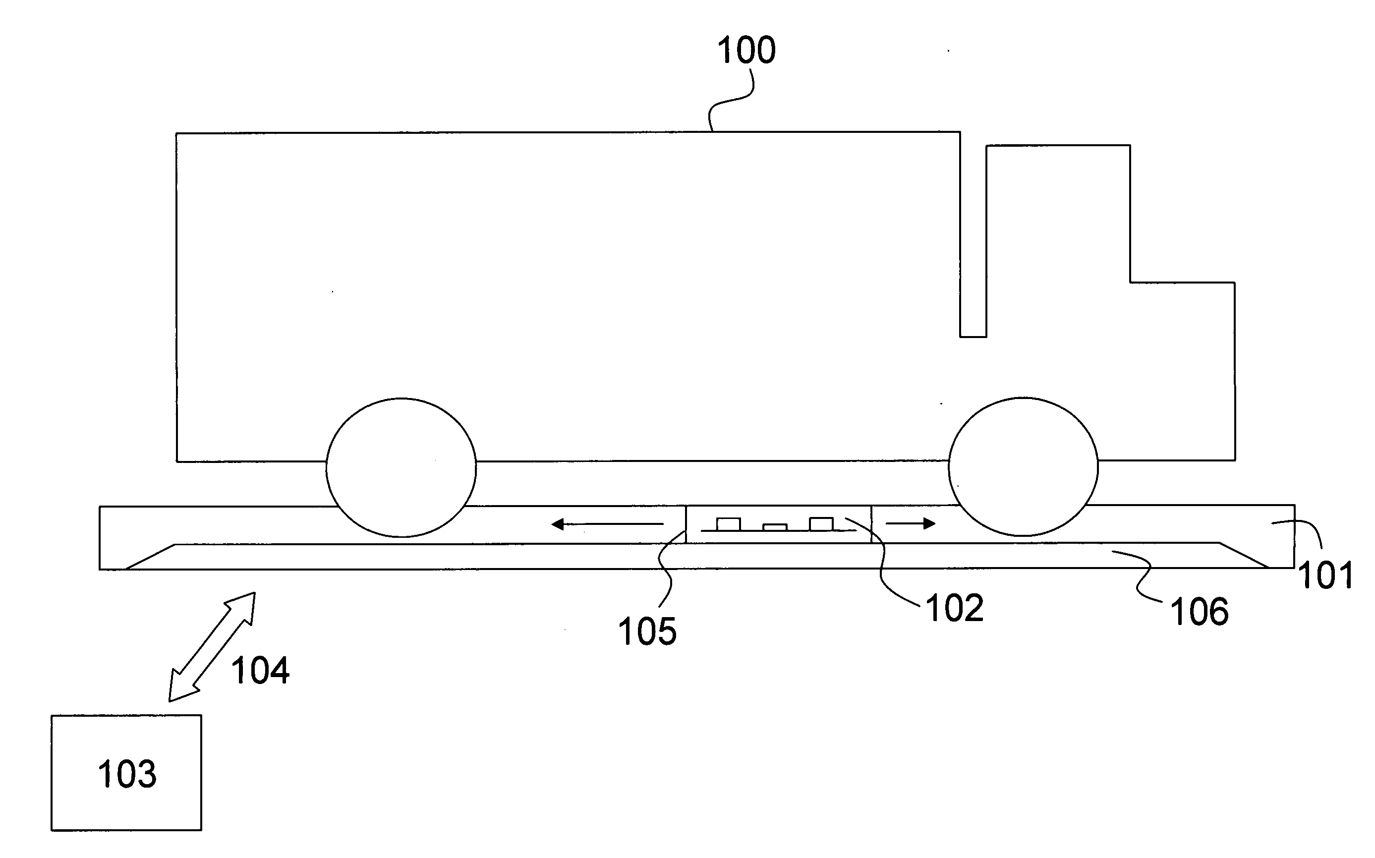
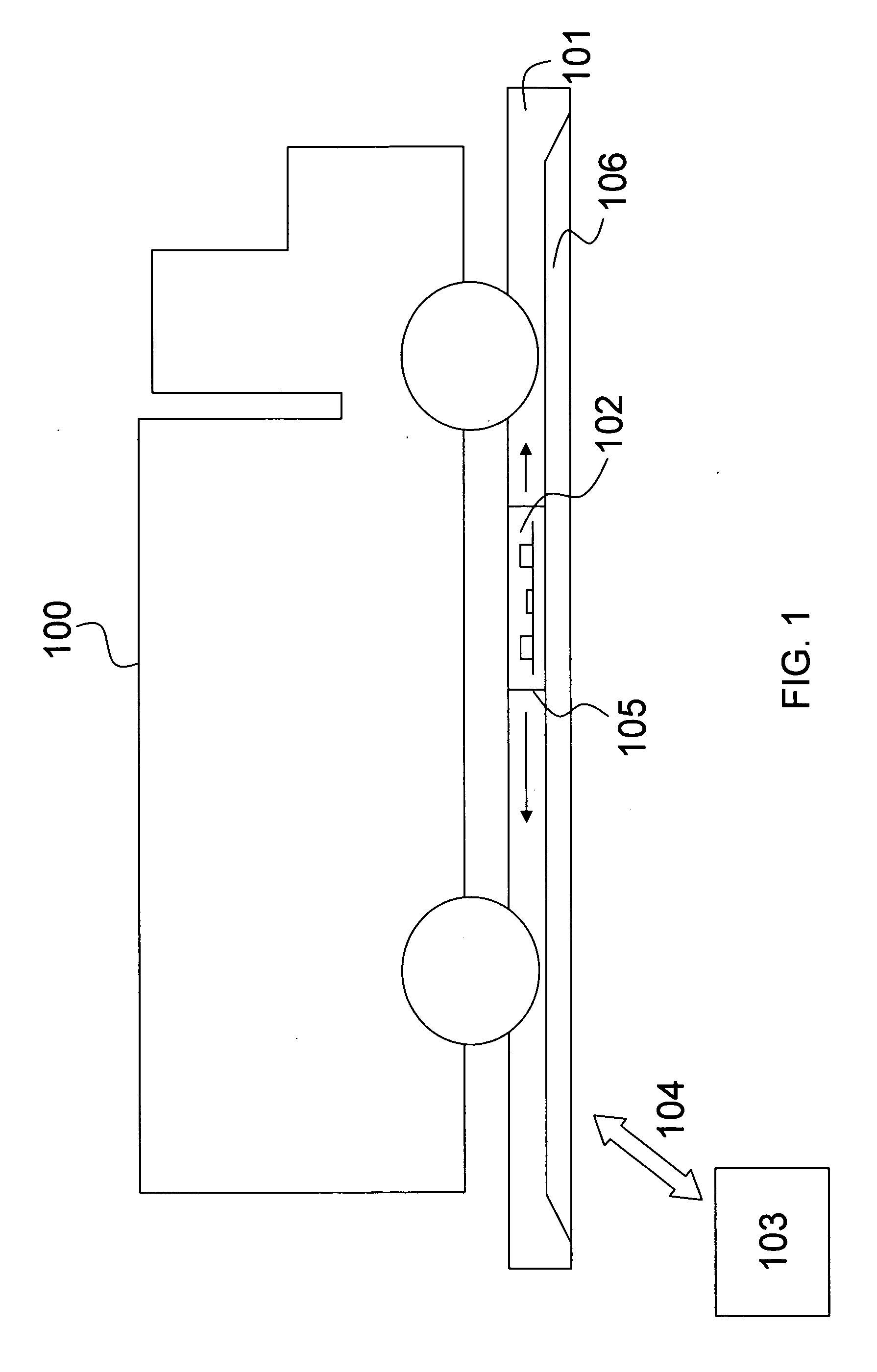
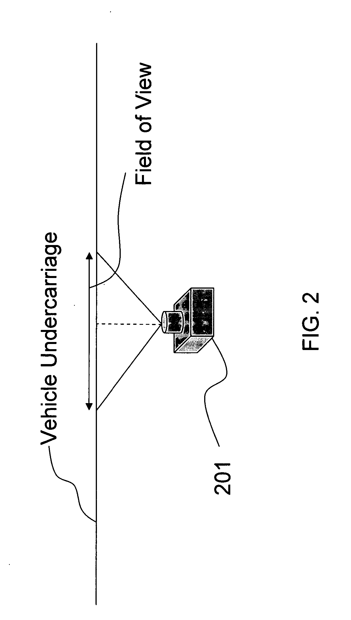
[0044] Selected embodiments of the invention provide an under vehicle inspection system comprising a single camera adapted to capture a full width image of a vehicle undercarriage by performing a single scan, or pass, along the length of the vehicle undercarriage. The camera is typically mounted in a camera carriage adapted to move along the length of the vehicle undercarriage on a track associated with a vehicle undercarriage inspection platform.

[0045] The term “vehicle undercarriage inspection platform” (or “platform” for short) is used throughout this description to denote any physical structure capable of receiving and / or supporting a vehicle, in whole or in part, in such a manner that the camera may view a significant portion of the vehicle's ...


PUM


Abstract

An under vehicle inspection system comprises a single camera adapted to capture a full width image of a vehicle undercarriage in a single scan. The camera has a viewing distance from the vehicle undercarriage, as measured along the optical axis of the camera, that is greater than a Euclidean distance between the camera and a point where the optical axis meets the vehicle undercarriage.

Description

CROSS REFERENCE TO RELATED APPLICATIONS [0001] This application is a continuation-in-part of U.S. patent application Ser. No. 11 / 389,182 filed Mar. 27, 2006 (the '182 application), which is a continuation-in-part of U.S. patent application Ser. No. 11 / 045,074 filed on Jan. 31, 2005 (the '074 Application), the respective disclosures of which are hereby incorporated by reference in their entirety.STATEMENT OF GOVERNMENT SPONSORED RESEARCH [0002] One or more agencies of the United States Government have a paid-up license in this invention and may in limited circumstances possess the right to require the patent owner to license others on reasonable terms as provided by the terms of Government Contract Number N00164-04-C-6653 awarded by the Naval Surface Warfare Center, Crane, Ind.BACKGROUND OF THE INVENTION [0003] 1. Field of the Invention [0004] Embodiments of the invention relate generally to an under vehicle inspection system. More particularly, embodiments of the invention relate to...

Claims


Application Information

Patent Timeline
Patent Type & Authority Applications(United States)
IPC IPC(8): H04N7/18
CPCH04N7/181
Inventor RILEY, LARRY E.
Owner RILEY LARRY E
Why Eureka
Try Eureka