Interference suppression techniques

a suppression technique and interference technology, applied in frequency response correction, instruments, loudspeakers, etc., can solve the problems of hearing aid devices not allowing selective amplification of desired sounds, separation of desired sounds from unwanted sounds, and difficulty in extracting desired signals in the presence of interference signals

Inactive Publication Date: 2007-02-08
JONES DOUGLAS +9
View PDF99 Cites 26 Cited by
  • Summary
  • Abstract
  • Description
  • Claims
  • Application Information

AI Technical Summary

Benefits of technology

[0006] One form of the present invention includes a unique signal processing technique using tw...

Problems solved by technology

The difficulty of extracting a desired signal in the presence of interfering signals is a long-standing problem confronted by acoustic engineers.
This problem impacts the design and construction of many kinds of devices such as systems for voice recognition and intelligence gathering.
Especially troublesome is the separation of desi...

Method used


Image

  • Interference suppression techniques
  • Interference suppression techniques
  • Interference suppression techniques

Examples


Embodiment Construction

[0018] While the present invention can take many different forms, for the purpose of promoting an understanding of the principles of the invention, reference will now be made to the embodiments illustrated in the drawings and specific language will be used to describe the same. It will nevertheless be understood that no limitation of the scope of the invention is thereby intended. Any alterations and further modifications of the described embodiments, and any further applications of the principles of the invention as described herein are contemplated as would normally occur to one skilled in the art to which the invention relates.

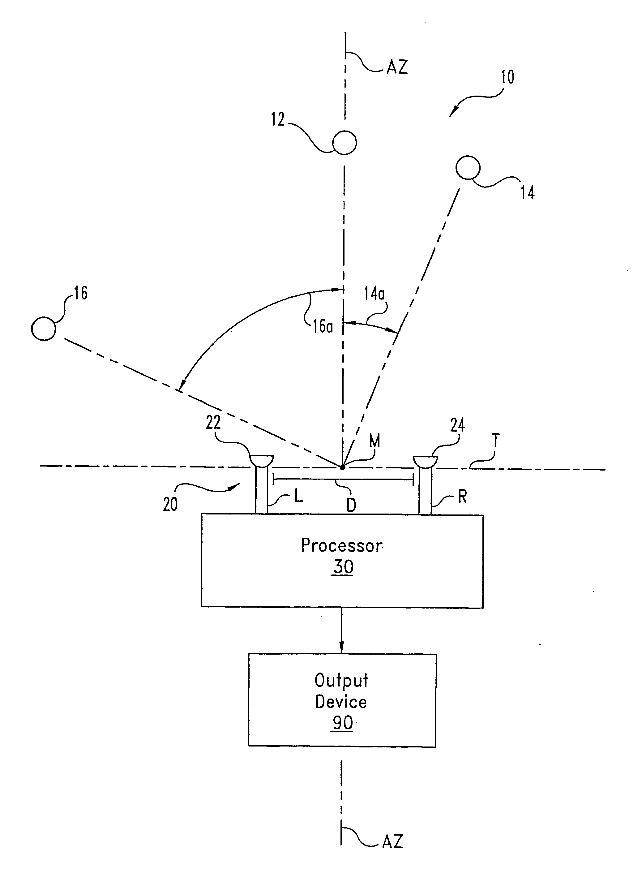
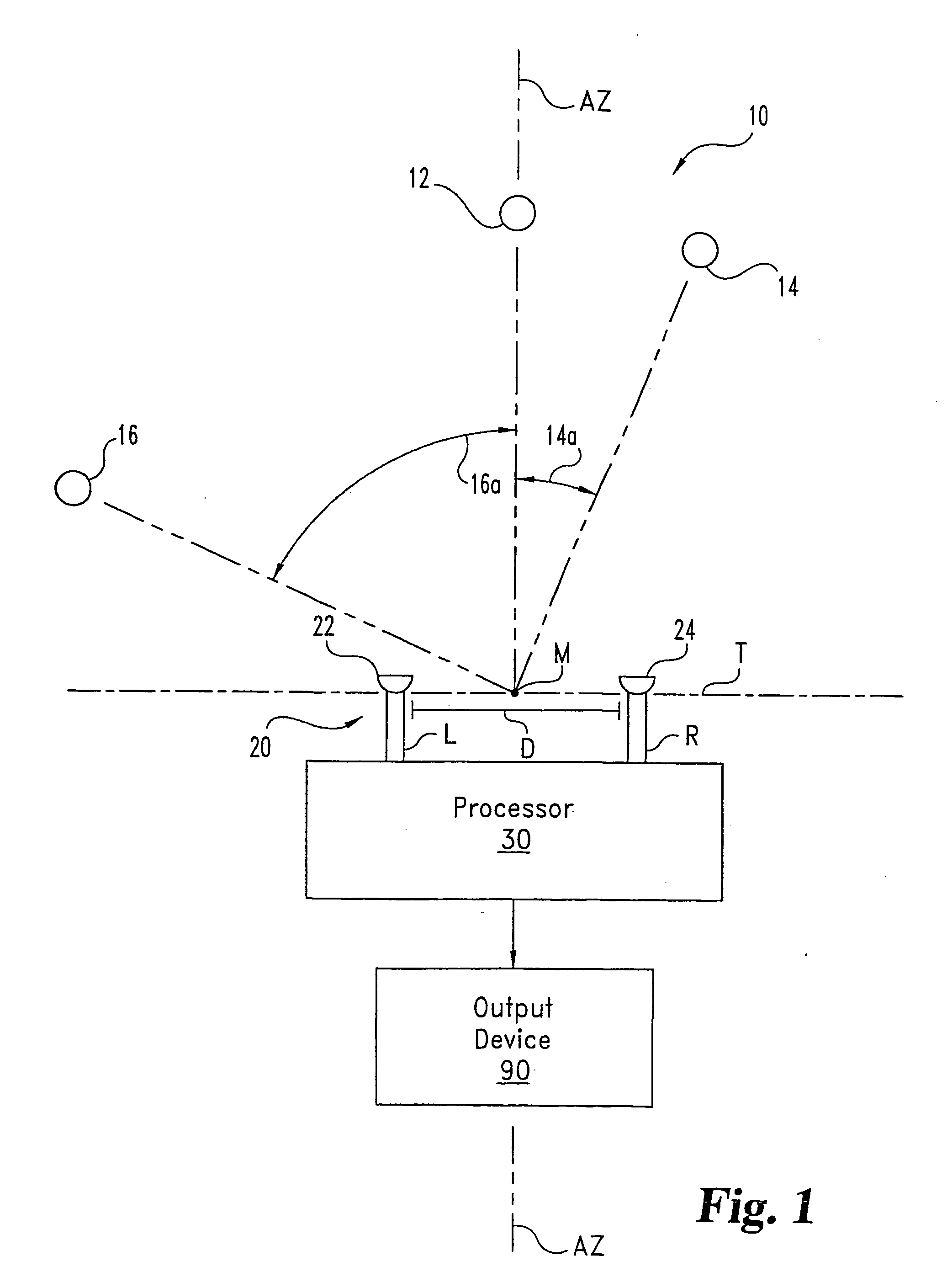
[0019]FIG. 1 illustrates an acoustic signal processing system 10 of one embodiment of the present invention. System 10 is configured to extract a desired acoustic excitation from acoustic source 12 in the presence of interference or noise from other sources, such as acoustic sources 14, 16. System 10 includes acoustic sensor array 20. For the example illus...


PUM


Abstract

System (10) is disclosed including an acoustic sensor array (20) coupled to processor (42). System (10) processes inputs from array (20) to extract a desired acoustic signal through the suppression of interfering signals. The extraction/suppression is performed by modifying the array (20) inputs in the frequency domain with weights selected to minimize variance of the resulting output signal while maintaining unity gain of signals received in the direction of the desired acoustic signal. System (10) may be utilized in hearing aids, voice input devices, surveillance devices, and other applications.

Description

CROSS-REFERENCE TO RELATED APPLICATIONS [0001] The present application is a continuation-in-part of U.S. patent application Ser. No. No. 09 / 568,430 filed on May 10, 2000, and is related to: U.S. patent application Ser. No. No. 09 / 193,058 filed on 16 Nov. 1998, which is a continuation-in-part of U.S. patent application Ser. No. 08 / 666,757 filed Jun. 19, 1996 (now U.S. Pat. No. 6,222,927 B1); [0002] U.S. patent application Ser. No. 09 / 568,435 filed on May 10, 2000; and U.S. patent application Ser. No. 09 / 805,233 filed on Mar. 13, 2001, which is a continuation of International Patent Application Number PCT / US99 / 26965, all of which are hereby incorporated by reference.GOVERNMENT RIGHTS [0003] The U.S. Government has a paid-up license in this invention and the right in limited circumstances to require the patent owner to license others on reasonable terms as provided for by DARPA Contract No. ARMY SUNY240-6762A and National Institutes of Health Contract No. R21DC04840.BACKGROUND OF THE I...

Claims


Application Information

Patent Timeline
IPC IPC(8): H04B15/00G10L21/0208G10L21/0232G10L25/00H04R3/00H04R3/04H04R25/00
CPCG10L2021/02165H04R3/005H04R2430/20H04R2201/403H04R2225/43H04R25/407
Inventor JONES, DOUGLASLOCKWOOD, MICHAELBILGER, ROBERTBILGER, CAROLYNFENG, ALBERTLANSING, CHARISSAO'BRIEN, WILLIAMWHEELER, BRUCEELLEDGE, MARKLIU, CHEN
Owner JONES DOUGLAS
Why Eureka
Try Eureka