Energy dissipation device with elevated action force

a technology of energy dissipation device and action force, which is applied in the direction of spring/damper, vibration damper, railway components, etc., can solve the problems of insufficient dissipation of incident energy by the attractive and impact device, exposed to extreme stress, damaged or even completely destroyed,

Inactive Publication Date: 2007-02-15
VOITH TURBO SCHARFENBERG
View PDF7 Cites 23 Cited by
  • Summary
  • Abstract
  • Description
  • Claims
  • Application Information

AI Technical Summary

Benefits of technology

[0016] On the basis of the problem described, the objective of the present invention is to extend an energy dissipation device of the type stated in the introduction in such a manner that for one thing the impact energy transferred over the energy dissipation device by an extreme impact can be reliably dissipated and that for another thing the force-path characteristic curve of the energy dissipation device can be adapted to individual applications as precisely as possible.
[0032] In order to achieve the fundamentally necessary initial securement of the energy dissipation elements in position between the two force-transferring elements, it is provided in a particularly preferred form of embodiment that the energy dissipation device comprises in addition at least one clamping element in order to initially secure the energy dissipation elements in position for the tractive and impact forces occurring in normal operation in a manner such that they are free of play between the force-transferring elements, at least in part. The energy dissipation elements' play-free initial securement in position in the energy dissipation device is advantageous since in this way a predictable course of energy dissipation is made possible. In particular, it can be ensured in this way that even those forces, which have, along with a force component in the longitudinal direction of the energy dissipation device, also a force component in the transverse direction of the energy dissipation device can be reliably and predictably absorbed and dissipated with the aid of the energy dissipation elements.

Problems solved by technology

In each case the tractive and impact device is not sufficient for the dissipation of the incident energy.
Thus this impact protection device is then no longer incorporated in the energy dissipation concept of the entire vehicle so that the occurring impact energy is transferred directly to the frame of the vehicle.
With this, it is exposed to extreme stresses and under certain circumstances is damaged or even entirely destroyed.
In the case of rail vehicles there is the danger of derailing.
Due to the fact that energy dissipation devices in which an energy dissipation element formed to be destructible is integrated have as a rule a rectangular characteristic curve predefined by the energy dissipation element (deformation tube), it is not possible to adapt such energy dissipation devices precisely to certain applications.
The use of energy dissipation devices in which an energy dissipation element operating hydrostatically is used, and which therefore have an characteristic curve which increases essentially linearly, is also frequently not suitable for many applications since the maximum energy uptake of the corresponding energy dissipation elements is often too small.
However, such a realization can frequently be used in practice only to a limited extent since it is not permissible to apply the fundamentally necessary initial securement in position of the energy dissipation element (deformation element) to such shearing elements.

Method used


Image

  • Energy dissipation device with elevated action force
  • Energy dissipation device with elevated action force
  • Energy dissipation device with elevated action force

Examples


Embodiment Construction

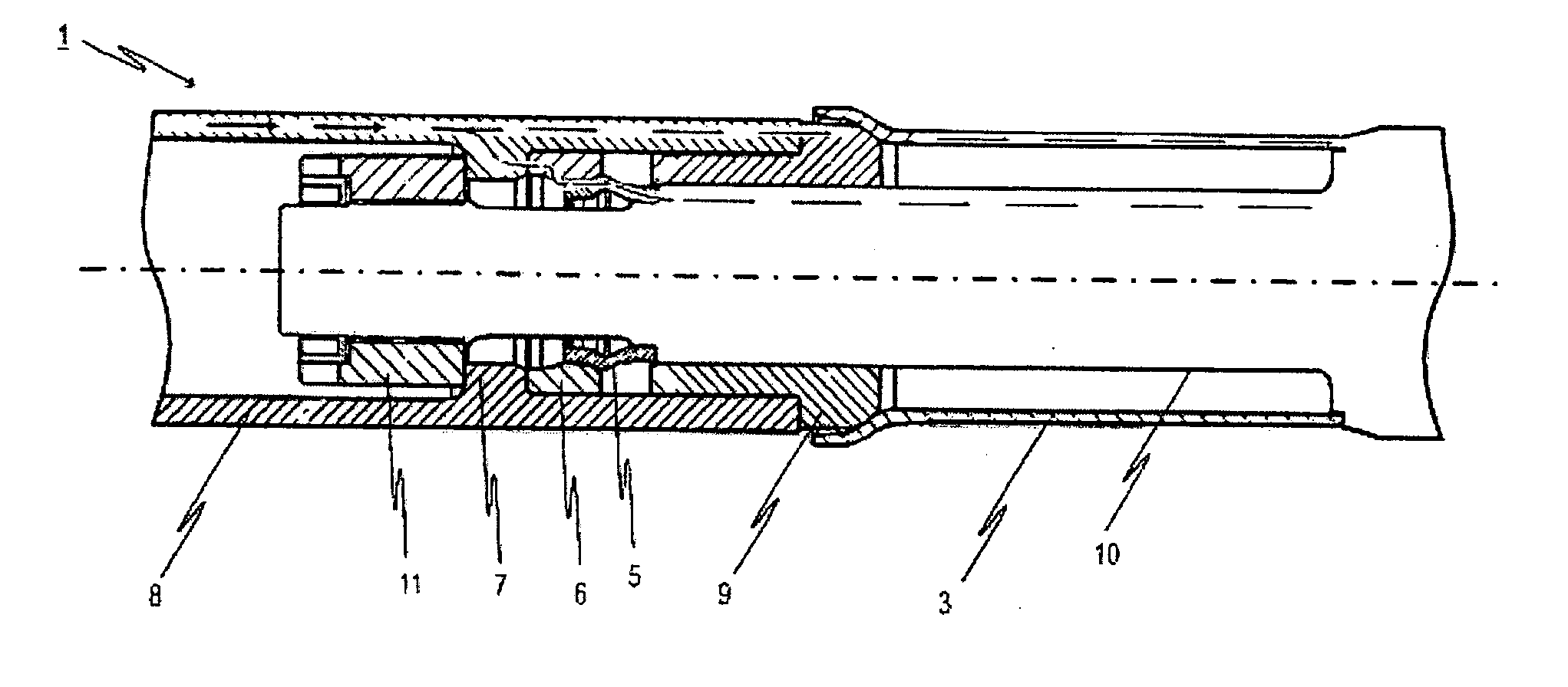
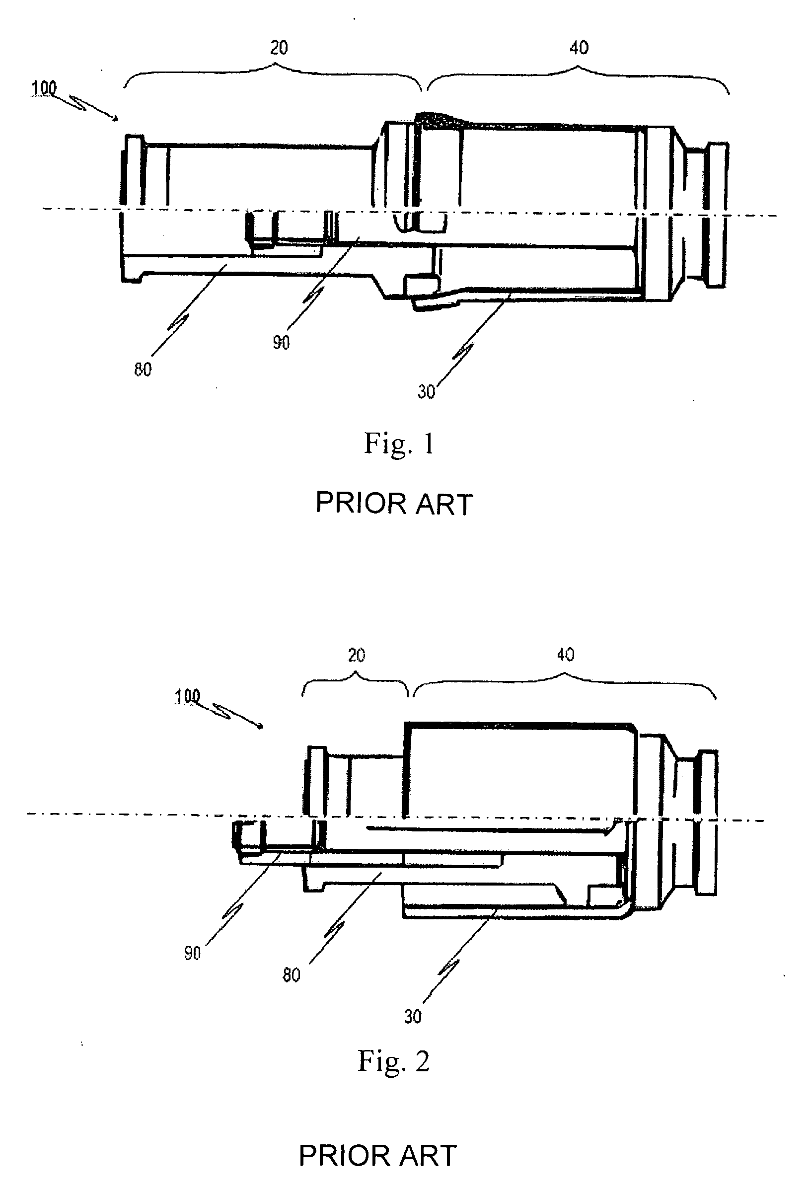
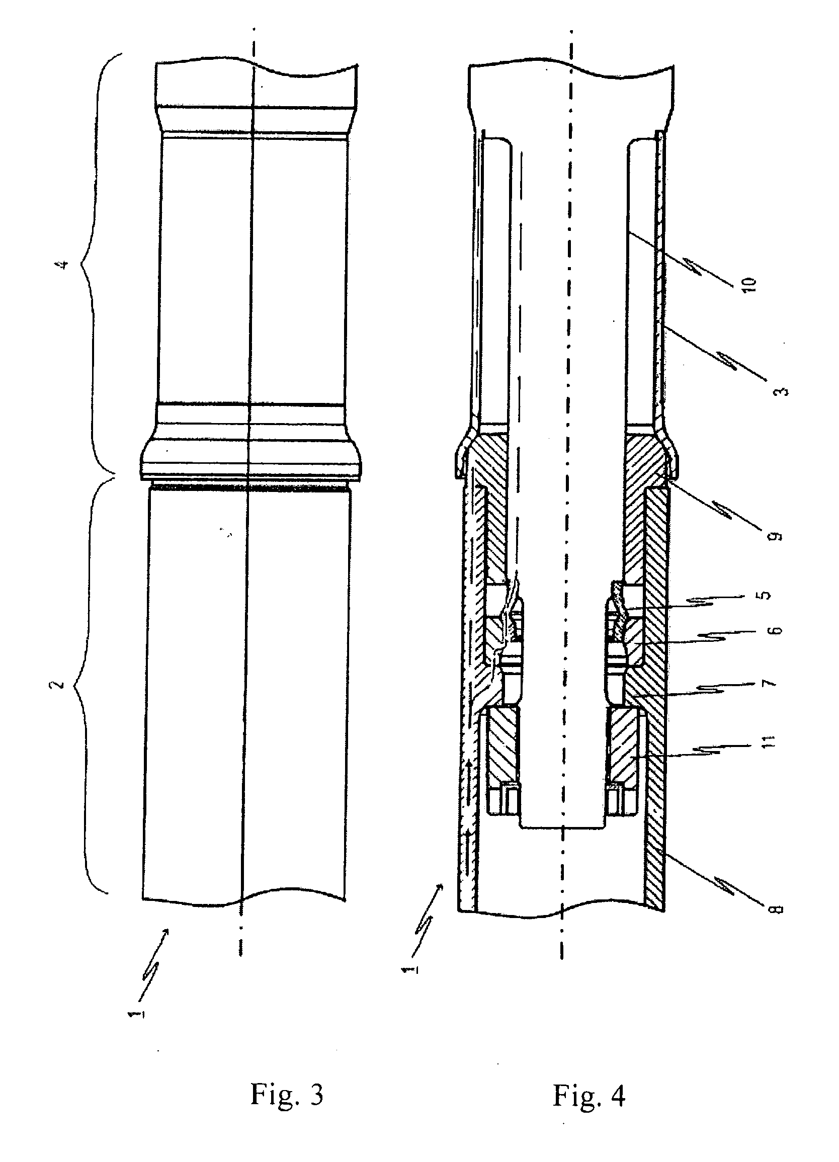
[0042]FIG. 1 shows an energy dissipation device 100 from the state of the art, where the lower half of the energy dissipation device 100 is represented in partial section. The energy dissipation device 100 comprises a first force-transferring element 20, a second force-transferring element 40, and an energy dissipation element 30 which is formed here as a deformation tube. The force-transferring elements 20, 40 are connected to one another via the energy dissipation element 30 in a force-locking manner such that tractive and impact forces can be transferred in the longitudinal direction of the energy dissipation device 100. In the transfer of the forces the corresponding force flow runs nearly completely through the energy dissipation element 30 integrated in the energy dissipation device 100. The first force-transferring element 20 has a first supporting body 80 which is embodied here as a tubular element. The second force-transferring element 40 has a second supporting body 90 emb...


PUM


Abstract

The present invention relates to an energy dissipation device with a first force-transferring element, a second force-transferring element, and a first and second energy dissipation element which are disposed in the energy dissipation device such that the force flow taking place during the transfer of the tractive and impact forces in the longitudinal direction of the energy dissipation device runs parallel through the two energy dissipation elements. By the activation behavior of the individual energy dissipation elements being chosen appropriately, the total characteristic curve of the energy dissipation device can be precisely determined in advance. In particular, the invention makes possible the construction of energy dissipation devices with force-path characteristic curves with regions of the characteristic curve, which fall off sharply. For this, characteristic curve contours are possible in particular in which, to trigger the energy dissipation device, a greater force is required than during the actual energy dissipation.

Description

CROSS-REFERENCE TO RELATED APPLICATIONS [0001] The present application claims priority to European Patent Office Application No. EP05017411.9, filed Aug. 10, 2005. TECHNICAL FIELD [0002] The present invention relates to an energy dissipation device. BACKGROUND OF THE INVENTION [0003] The present invention relates to an energy dissipation device with a first force-transferring element, a second force-transferring element, and a first energy dissipation element, where the force-transferring elements are, with the aid of the first energy dissipation element, connected to one another in a force-locking manner such that tractive and impact forces can be transferred in the longitudinal direction of the energy dissipation device by the fact that the force flow taking place during the transfer of forces runs at least partially through the first energy dissipation element, where the first energy dissipation element is designed in such a manner that up to a determinable first amount of energy...

Claims


Application Information

Patent Timeline
Patent Type & Authority Applications(United States)
IPC IPC(8): F16F7/12
CPCB61G9/10F16F7/125B61G11/16
Inventor KEMPER, ANDREAS
Owner VOITH TURBO SCHARFENBERG
Why Eureka
Try Eureka