
Digital section real-time scanning and automatic focusing tracking method

A digital slicing and auto-focusing technology, applied in microscopes, optics, television, etc., can solve problems such as limitations and limited scanning speed improvement, and achieve the effect of reducing requirements, improving scanning speed, and small structural changes

Active Publication Date: 2014-02-19
MOTIC CHINA GRP CO LTD
View PDF3 Cites 25 Cited by
  • Summary
  • Abstract
  • Description
  • Claims
  • Application Information

AI Technical Summary

Problems solved by technology

The main disadvantage of this method is that the scanning speed is limited. This is because the optical field of view of the microscope has a certain size. Taking the 20X objective lens as an example, the observation range of almost all microscopes is between 1-1.3 mm. Only one of the rectangular areas is covered, and its long side is about 0.9 mm. If the standard resolution of the digital slice scanning system in the industry is 0.25 μm / pixel, then the maximum number of pixels in a line in the horizontal direction is 3600 pixels, and exceeding this value will exceed Visible field of view, so the maximum number of pixels of a digital camera should not exceed 8 megapixels, which also limits the improvement of scanning speed

Method used


Image

  • Digital section real-time scanning and automatic focusing tracking method
  • Digital section real-time scanning and automatic focusing tracking method
  • Digital section real-time scanning and automatic focusing tracking method

Examples


Embodiment

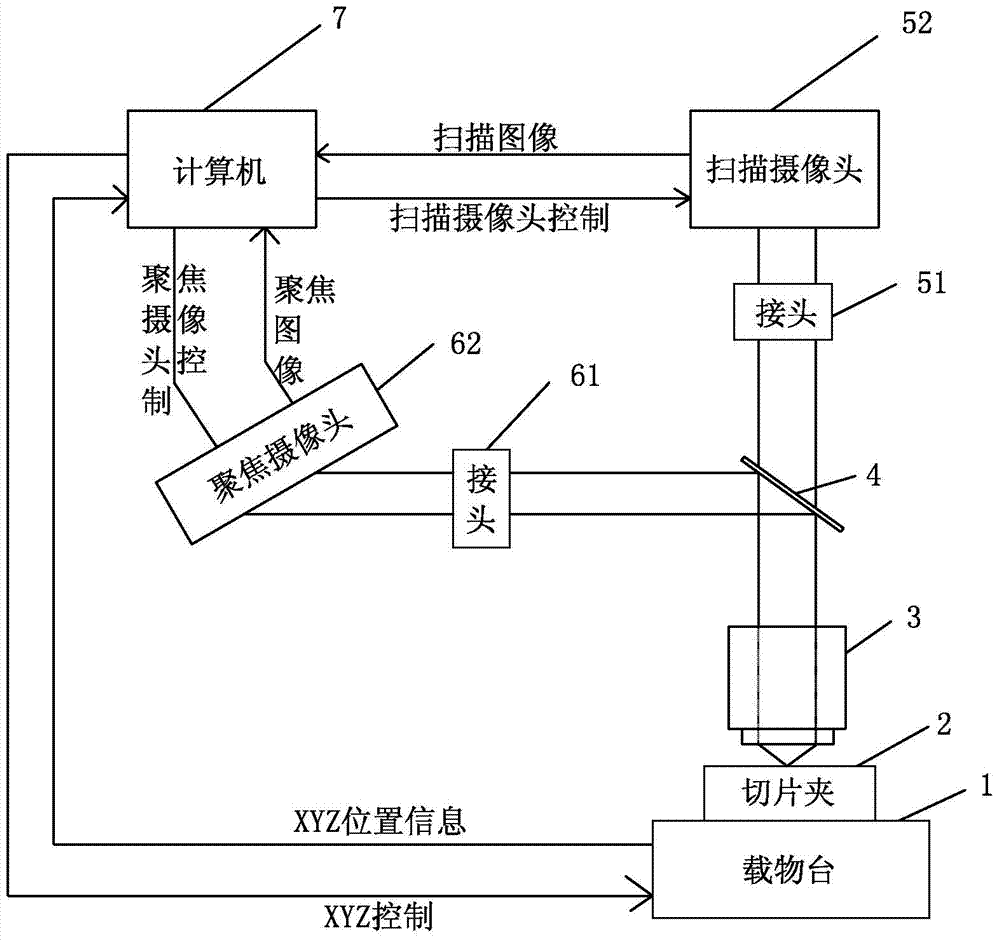
[0030] Such as figure 1 As shown, a digital slice real-time scanning automatic focus tracking method of the present invention, its hardware consists of stage 1, stage X, Y, Z control device, slice holder 2, objective lens 3, beam splitting prism 4, scanning camera The optical connector 51, the scanning camera 52, the focusing camera optical connector 61, the focusing camera 62, and the computer processing system 7 are all conventional components, wherein the focusing controller controls the stage to move along the Z axis, and the displacement controller controls the carrier The object stage moves along the X and Y axes, the scanning camera optical joint 51 and the scanning camera 52 form a scanning imaging device, and the focusing camera optical joint 61 and the focusing camera 62 form a focusing imaging device. The computer processing system 7 controls the X, Y, and Z control devices to move the stage in three directions. The sliced ​​image passes through the objective lens 3...


PUM


Abstract

The invention discloses a digital section real-time scanning and automatic focusing tracking method. According to the method, a scanning imaging device and a focusing imaging device are adjusted to have the same view fields; in the digital section scanning process, the focusing imaging device is used for tracking and obtaining the position of a focal plane of the view field rapidly in the movement process of an objective table, a dynamic local section surface mathematical model is built through a computer processing system, the focal plane of a nearby view field is predicted, through continuous dynamic analysis and focusing positioning, it is guaranteed that the scanning imaging device can also obtain a clear focal plane image of each view field in time in the movement process of the objective table, the focal plane position of the nearby view field can be tracked timely and predicted accurately according to the method, focusing action does not need to be performed repeatedly in the nearby view field, and only a single view field image of each view field where the objective table passes by needs to be captured in the continuous movement process of the objective table. The method is high in focusing accuracy, high in speed and capable of achieving rapid scanning and guaranteeing high-resolution digital section images.

Description

technical field [0001] The invention relates to an automatic focus tracking method for real-time scanning of digital slices. Background technique [0002] In the scanning of digital slices with an automatic microscope, there are two key indicators, one is the speed of scanning slices, and the other is the quality of scanned images, but these two key indicators are mutually restricted. [0003] In order to scan slices as fast as possible, the more classic method is to define several points in the tissue area under the scanning objective lens for the slices, and focus on each point one by one to collect its X, Y position and Z position of the focal plane, using this The 3-dimensional coordinate points establish an overall focusing mathematical model on the surface of the sliced ​​tissue. The established mathematical model can be linear or non-linear, and this mathematical model represents the overall convex-convex change on the surface of the sliced ​​tissue. During the slice...

Claims


Application Information

Patent Timeline
Patent Type & Authority Applications(China)
IPC IPC(8): G02B21/36H04N5/232
Inventor 贾守礼康军陈进高志刚
Owner MOTIC CHINA GRP CO LTD
Learn More