Terahertz wave fast imaging scanner

An imaging scanning and terahertz technology, applied in measurement devices, material analysis by optical means, instruments, etc., can solve the problems of expensive terahertz wave detection devices, complex and expensive imaging systems, poor consistency and stability, etc. Achieve the effect of easy production and debugging, low cost and fast imaging

Inactive Publication Date: 2010-09-15
CAPITAL NORMAL UNIVERSITY +1
View PDF4 Cites 31 Cited by
  • Summary
  • Abstract
  • Description
  • Claims
  • Application Information

AI Technical Summary

Problems solved by technology

[0002] There are several existing terahertz wave scanning methods: 1. Mechanical scanning imaging: it uses mechanical motion to obtain the target characteristics of a scene with a large field of view, but mechanical scanning imaging takes a certain amount of time in the process of acquiring signals, which is very difficult. Difficult to achieve real-time imaging
2. Synthetic aperture imaging: mainly arrange N small antennas with real apertures according to a certain rule, and process the received signals to obtain the effect equivalent to a synthetic large aperture antenna, but the imaging system is too complicated and expensive , and the space required for the interference array is large
3. Focal plane imaging: arranging multiple receiving units on the focal plane of the focusing antenna, using the different deflection of each feed source to generate multiple beams with different directions to cover the field of view, but the reception of terahertz bands at this stage Units are difficult to make and extremely expensive
4. Use the galvanometer for two-dimensional scanning imaging. In order to obtain a high-resolution image, the galvanometer needs to be very large and needs to swing at a high frequency. This is very difficult to achieve
[0005] However, because the price of terahertz wave detection devices is still very expensive at present, and the consistency and stability of their manufacture are still relatively poor, so the current terahertz wave detection devices cannot achieve the convenient formation of two-dimensional arrays like CCD or infrared focal plane array. dimensional image, so using fewer terahertz wave detection devices and using optomechanical scanning is the most realistic implementation technology of terahertz wave fast imaging

Method used


Image

  • Terahertz wave fast imaging scanner
  • Terahertz wave fast imaging scanner
  • Terahertz wave fast imaging scanner

Examples


Embodiment Construction

[0033] In order to better understand the shape, structure and characteristics of the present invention, preferred embodiments will be listed below and described in detail with reference to the accompanying drawings.

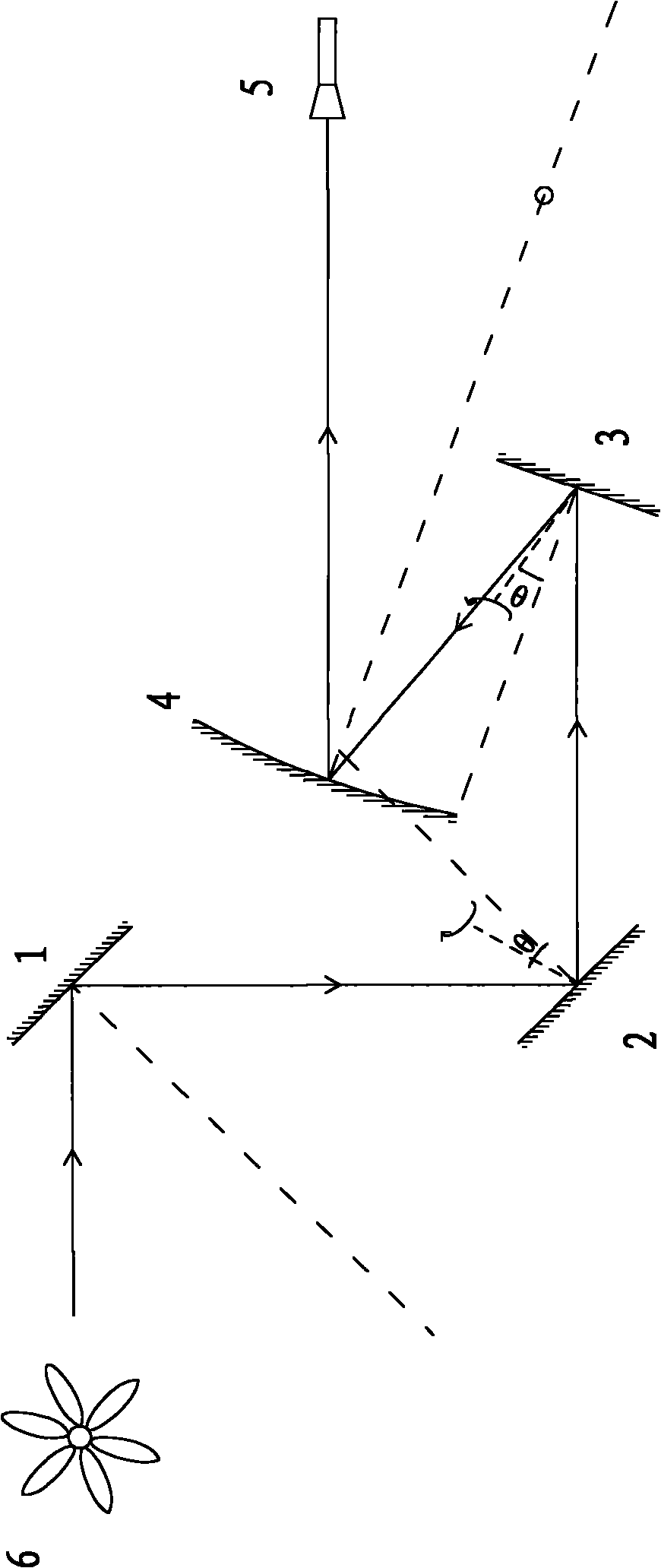
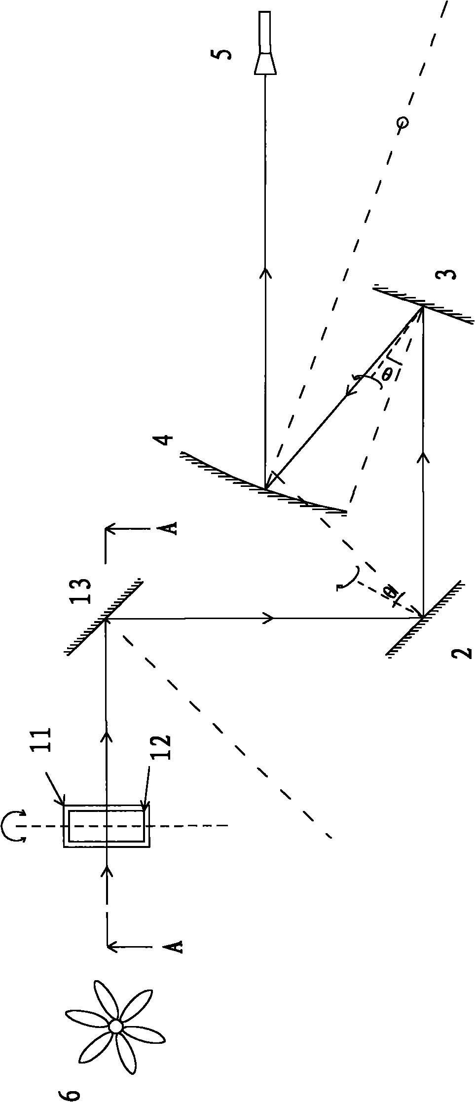
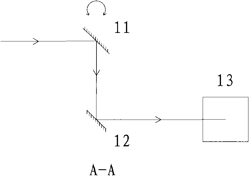
[0034] A terahertz wave rapid imaging scanning device of the present invention is used to scan the object to be scanned, including a frame scanning mirror group, which is located behind the object to be scanned, and is used to scan the object to be scanned longitudinally; a line scanning mirror group is arranged on the frame scanning mirror The optical path after the group is used to horizontally scan the object to be scanned; the concave mirror is located on the optical path behind the line scanning mirror group to converge the terahertz wave; the terahertz wave detector is located on the optical path behind the concave mirror to receive the scanning signal .

[0035] figure 1 It is the front view of the first embodiment of the present invention, taking the opt...


PUM


Abstract

The invention relates to an imaging device for performing large field of view and fast scanning on terahertz waves by using a fast scanning device. The terahertz wave fast imaging scanner is used for scanning objects to be scanned, and comprises a frame scanning lens group, a row scanning lens group, a concave mirror and a terahertz wave detector. The frame scanning lens group is positioned behind the objects to be scanned and is used for longitudinally scanning the objects to be scanned; the row scanning lens group is arranged on a light path behind the frame scanning lens group and is used for transversely scanning the objects to be scanned; the concave mirror is positioned on the light path behind the row scanning lens group and is used for converging the terahertz waves; and the terahertz wave detector is positioned on the light path behind the concave mirror and is used for receiving scanning signals. Due to the adoption of the imaging mode of single point light machine scanning, the terahertz wave fast imaging scanner can realize fast imaging of the field of view, and make the whole imaging system have small volume, low cost and relatively easy manufacture and debugging. The terahertz wave fast imaging scanner can be applied to passive imaging modes, and also can be applied to active imaging modes.

Description

technical field [0001] The present invention relates to a scanning device for terahertz wave imaging, in particular, the present invention relates to an imaging device that utilizes a fast scanning device to perform large field of view and fast scanning for terahertz waves. Background technique [0002] There are several existing terahertz wave scanning methods: 1. Mechanical scanning imaging: it uses mechanical motion to obtain the target characteristics of a scene with a large field of view, but mechanical scanning imaging takes a certain amount of time in the process of acquiring signals, which is very difficult. Difficult to achieve real-time imaging. 2. Synthetic aperture imaging: mainly arrange N small antennas with real apertures according to a certain rule, and process the received signals to obtain the effect equivalent to a synthetic large aperture antenna, but the imaging system is too complicated and expensive , and the space required for the interference array ...

Claims


Application Information

Patent Timeline
Patent Type & Authority Applications(China)
IPC IPC(8): G01N21/17G02B26/10
Inventor 张存林邓朝赵跃进朱维文张雅琳
Owner CAPITAL NORMAL UNIVERSITY
Why Eureka
Try Eureka