

Scanning method and device for microscopic section
A microslicing and scanning device technology, applied in the field of microscopes, can solve problems such as stop-and-go, slow speed, and complex control, and achieve the effects of low control accuracy, reduced system cost, and increased scanning speed
- Summary
- Abstract
- Description
- Claims
- Application Information
AI Technical Summary
Problems solved by technology
Method used
Image

Examples
Embodiment 1
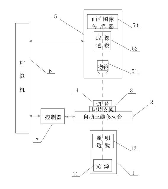
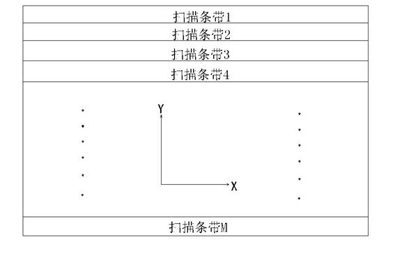
[0037] Such as figure 1 , 3 Shown in , 4, a kind of scanning method of microsection, first place the slice 4 to be measured on the automatic three-dimensional mobile platform 2, divide into several continuous scanning strips along its longitudinal direction, the scanning strip of each scanning strip The width is set to the size of the corresponding object field of view of the area array image sensor 53 in the longitudinal direction, and each scanning strip is divided into several continuous scanning fields of view along the horizontal direction, and the length of each scanning field of view is set to The size of the corresponding object field of view of the area array image sensor 53 in the lateral direction;
[0038] a) The computer 6 controls the automatic three-dimensional mobile platform 2 through the controller 7 to drive the current scanning strip of the slice 4 to move continuously along the X direction (that is, the transverse direction), pass through the object field...
Embodiment 2
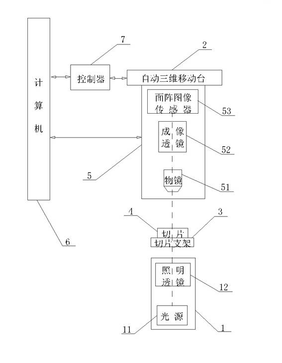
[0046] Such as figure 2 , 3 , 4, this embodiment is improved on the basis of embodiment one. In the first embodiment, the imaging system 5 is fixed, and the slice 4 moves with the automatic three-dimensional mobile platform 2; in the second embodiment, the slice 4 is fixed on the slice support frame 3, and the imaging system 5 is fixed on the automatic three-dimensional mobile platform 2. On the platform 3, the imaging system 5 moves along with the automatic three-dimensional mobile platform 3, and the specific steps are as follows:
[0047] First place the slice 4 to be measured on the slice support frame 3, and divide it into several continuous scanning strips along its longitudinal direction (ie, the Y direction). The width of each scanning strip is set to the corresponding object direction of the imaging system 5 The size of the field of view in the longitudinal direction, and each scanning strip is divided into several continuous scanning fields of view along the horiz...
Embodiment 3
[0056] Such as figure 1 , 3 As shown in , 4, this embodiment is improved on the basis of embodiment 1, aiming to further increase the scanning speed. Wherein, the area image sensor 53 has an external trigger function; the X direction and the Y direction of the automatic three-dimensional mobile platform 2 have high-precision displacement sensors such as gratings, so as to accurately know the moving distance of the automatic three-dimensional mobile platform 2, and in the X direction. After moving an accurate scanning field of view, the controller 7 outputs a signal as an external trigger signal of the area array image sensor 53 to start exposure. After the exposure is over, the computer 6 reads the image data of the area array image sensor 53 . Since all the image data obtained are accurate adjacent fields of view, they can be directly and seamlessly spliced without software algorithm stitching. At the same time, each scanning field of view has no overlapping rate, so the s...
PUM
 Abstract
Description
Claims
Application Information