Scanning optical coherent chromatography system from microlens or microprism array

An optical coherence tomography and micro-lens technology, applied in optics, optical components, instruments, etc., can solve the problems of high cost, low scanning speed, manual calibration error, etc., to facilitate mass production, reduce workload, and facilitate productization Effect

Inactive Publication Date: 2005-12-28
INST OF OPTICS & ELECTRONICS - CHINESE ACAD OF SCI
View PDF0 Cites 33 Cited by
  • Summary
  • Abstract
  • Description
  • Claims
  • Application Information

AI Technical Summary

Problems solved by technology

[0014] The technical problem of the present invention is to overcome the deficiencies of the prior art and provide an optical coherence tomography system that uses microlenses or microprism arrays for scanning, which can effectively solve the problems of

Method used


Image

  • Scanning optical coherent chromatography system from microlens or microprism array
  • Scanning optical coherent chromatography system from microlens or microprism array
  • Scanning optical coherent chromatography system from microlens or microprism array

Examples


Embodiment Construction

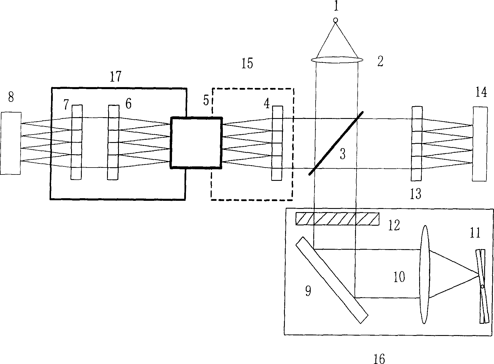
[0036] Such as image 3 As shown, the beam emitted by the point light source 1 is collimated into a parallel beam by the collimator 2, and the parallel beam is divided into two beams by the splitter 3, one of which is called the reference arm, passes through the fast delay line reference arm, and then returns to the beam splitter again On the prism 3, the main function of the fast delay line 16 is to realize the scanning of the longitudinal depth of the sample; the other bundle is called the sample arm, and at the output end of the multi-channel optical fiber coupling device 15, multiple The point light source in the optical fiber becomes a parallel light beam in the spatial optical path, and then is focused on the target object 8 by the second microlens or microprism array 7, and the light beam is reflected by the object 8 and is divided when passing through the multi-channel optical fiber coupling device 15 These beams meet the parallel beams reflected from the fast delay li...


PUM


Abstract

An optical coherent chromatographic system using micro-lens array to carry out scanning consists of light source, collimation lens, splitting prism, fibre coupling unit with multi-path, three micro-lens or micro-prism arrays , quick delay line , detector array and micro-shift device. It is featured as using above devices to change spot light source to be parallel beam , focusing it on object , meeting reflection light of object with reflection light from delay line on splitting prism for generating interference focused to detector array .

Description

technical field [0001] The invention relates to an optical coherence tomography technology, in particular to an optical coherence tomography system using microlens or microprism array scanning. technical background [0002] Optical coherence tomography is an emerging tomography. Compared with traditional tomography, it has the characteristics of high resolution, non-contact, writing, etc. With the development of optical coherence tomography, and various components With continuous improvement, its application fields are getting wider and wider. [0003] The general composition of traditional optical coherence tomography system is as follows: figure 1 As shown, this system adopts a point scanning method, mainly composed of a light source, a beam splitting prism, a reflector, and a photodetector. The light emitted by the light source is divided into two paths by the beam splitting prism: one path is called the sample arm, which is focused on the sample by the lens. , and then...

Claims


Application Information

Patent Timeline
IPC IPC(8): G02B26/10
Inventor 史国华张雨东陈凯戴云王海英李恩德
Owner INST OF OPTICS & ELECTRONICS - CHINESE ACAD OF SCI
Why Eureka
Try Eureka