Refrigerator receptacle

a technology of refrigerator and receptacle, which is applied in the field of refrigerator, can solve the problems of complicated and inconvenient process for getting food contained in the reception space b>29/b> of the basket, food in the reception space b>27/b>, and may interfere with the basket, so as to achieve the effect of reducing noise and facilitating and convenient manner

Active Publication Date: 2007-02-15
LG ELECTRONICS INC
View PDF33 Cites 49 Cited by
  • Summary
  • Abstract
  • Description
  • Claims
  • Application Information

AI Technical Summary

Benefits of technology

[0020] The inventive refrigerator receptacle is advantageous as follows: food can be put in the storage space or removed therefrom in an easy and convenient manner; food contained in the first tray is not damaged by the second tray when the first tray moves inwards / outwards, and vice versa; and minimum noise is generated by the trays when they are moved into / out of the storage space.

Problems solved by technology

However, the conventional refrigerator receptacle has the following problems.
As such, the process for getting food contained in the reception space 29 of the basket 27 is complicated and inconvenient.
This means that the food in the reception space 23 may interfere with the basket 27 on the move.

Method used


Image

  • Refrigerator receptacle
  • Refrigerator receptacle
  • Refrigerator receptacle

Examples


first embodiment

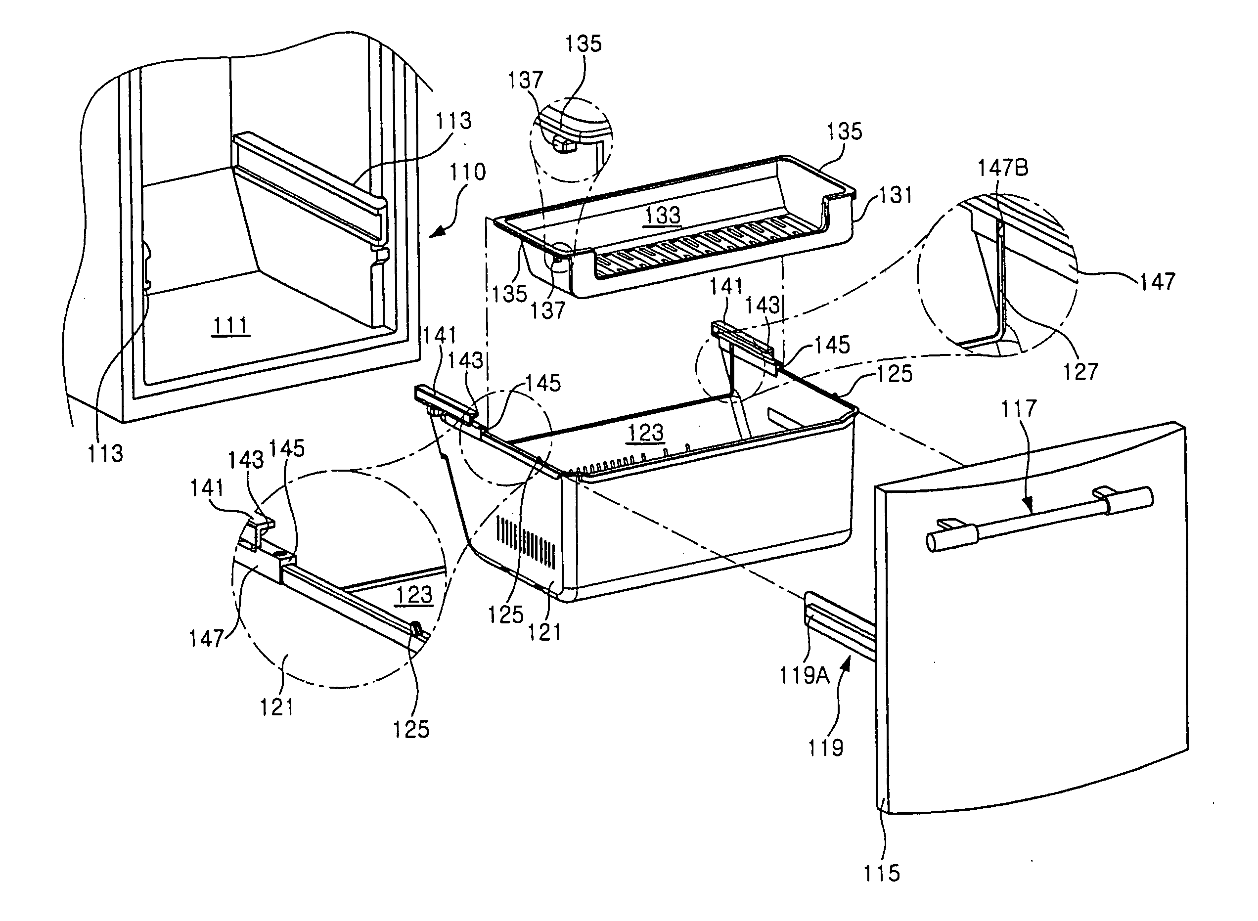
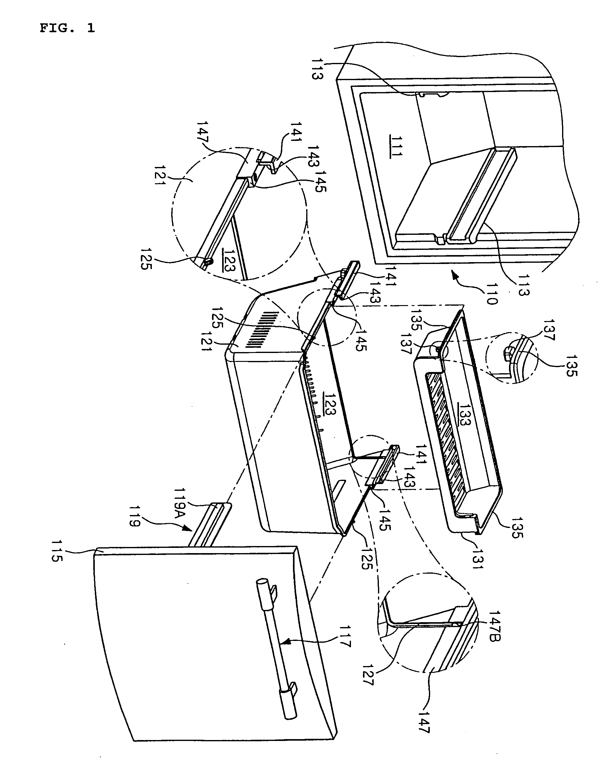
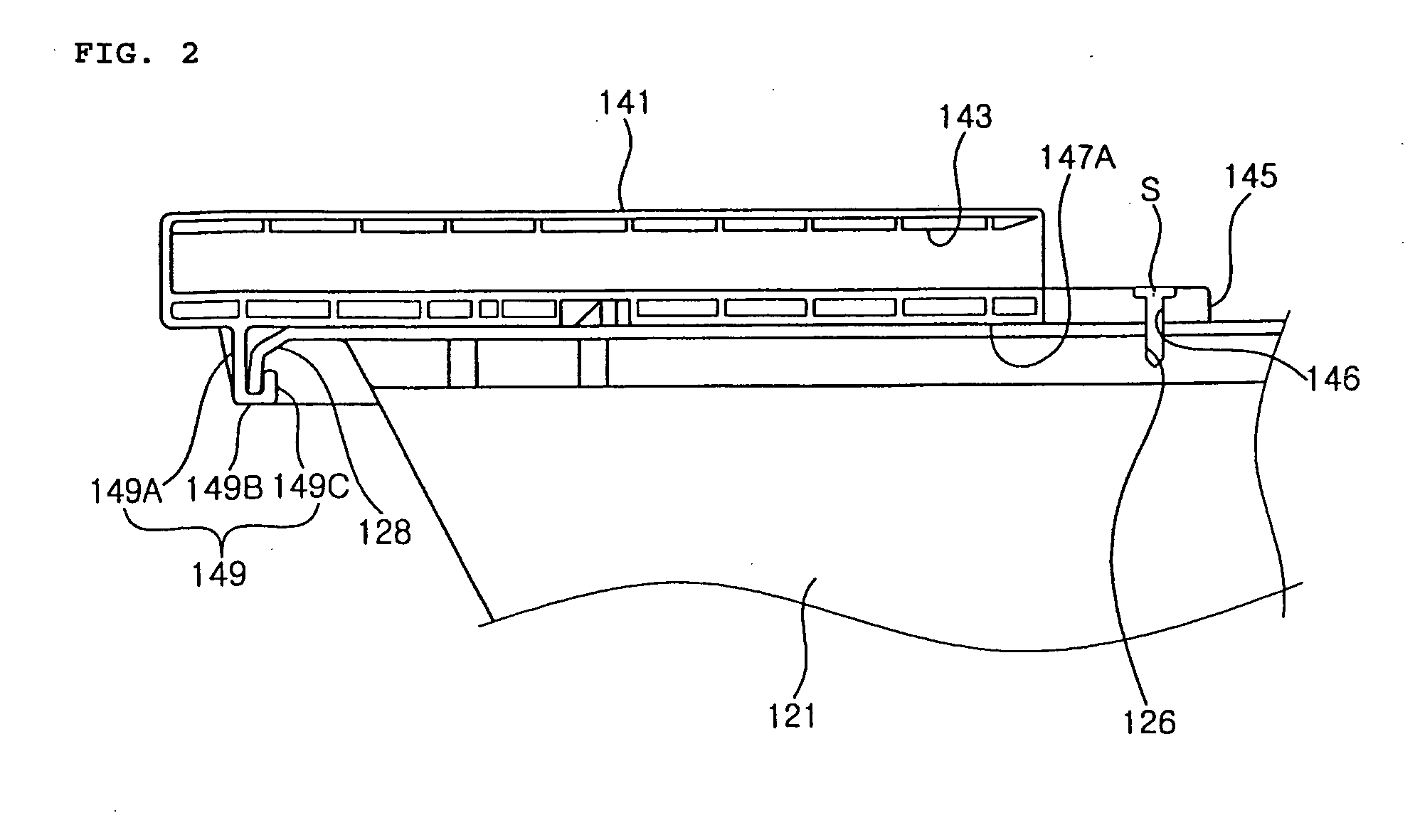
[0043] The latching steps 145 are positioned on the front end of the guide members 141, in order to prevent the second tray 131 from moving beyond a predetermined range in the backward direction relative to the first tray 121. According to the present invention, the front end of each guide member 141 has a level difference relative to the top of both lateral surfaces of the first tray 121, which corresponds to the thickness, and acts as a latching step 145.

[0044] Referring to FIG. 2, the guide members 141 have through-holes 146 formed on one side thereof, respectively, so that the fasteners S extend through the through-holes 146 to be fastened to the fastening holes 126. The through-holes 146 are positioned on the front end of the guide members 141 so as to correspond to the fastening holes 126 when the guide members 141 are installed on the first tray 121.

[0045] Each guide member 141 has insertion ribs 147 positioned on both ends of its bottom surface, respectively. The insertion ...

second embodiment

[0061] The construction of a refrigerator receptacle according to the present invention will now be described in detail with reference to the accompanying drawings.

[0062]FIG. 4 is an exploded perspective view briefly showing a refrigerator provided with a refrigerator receptacle according to a second embodiment of the present invention, and FIG. 5 is a perspective view partially showing the refrigerator receptacle according to the second embodiment of the present invention.

[0063] Referring to the drawings, a refrigerator body 210 has a storage space 211 defined therein and fixed rails 213 positioned on both lateral surfaces of the storage space 211, respectively, while being elongated forwards and backwards. The fixed rails 213 guide the inward / outward movement of a basket 221 (described later).

[0064] The fixed rails 213 have guide grooves 213A formed on their surfaces facing each other. Movable rails (not shown) of a basket frame 219 (described later) are inserted into the guide ...


PUM


Abstract

Disclosed is a refrigerator receptacle including a first tray adapted to move into/out of a storage space like a drawer, a reception space being defined in the first tray, the reception space having an upward opening; a second tray adapted to move in an inward/outward movement direction of the first tray, a reception space being defined in the second tray, the reception space having an upward opening; a guide member for guiding movement of the second tray, an insertion groove being formed on the guide member, an upper end of both lateral surfaces of the first tray being inserted into the insertion groove; and a fastener extending through one of the first tray and the guide member so as to be fastened to other of the first tray and the guide member.

Description

BACKGROUND OF THE INVENTION [0001] 1. Field of the invention [0002] The present invention relates to a refrigerator, and more particularly to a refrigerator receptacle removably installed in a storage space of a refrigerator so as to contain food. [0003] 2. Description of the Prior Art [0004]FIG. 6 is an exploded perspective view showing a conventional refrigerator receptacle. [0005] Referring to the drawing, a refrigerator body 10 has a storage space 11 defined therein. The storage space 11 has a front opening, as well as fixed rails 13 positioned on both lateral surfaces thereof while being elongated forwards and backwards. Support rods 15 are positioned on both lateral surfaces of the storage space 11 above the fixed rails 13. [0006] The body 10 has a door 17 for exposing / covering the storage space 11, a door handle 19 positioned on the front surface of the door 17 near its top, and a tray 21 fixed to the rear surface of the door 17. The tray 21 can be moved into / out of the stora...

Claims


Application Information

Patent Timeline
Patent Type & Authority Applications(United States)
IPC IPC(8): A47B96/04
CPCA47B2210/17F25D25/025F25D23/021
Inventor KOO, MIN BON
Owner LG ELECTRONICS INC
Why Eureka
Try Eureka