Image editing method, machine-readable storage medium, and terminal

Inactive Publication Date: 2014-09-18
SAMSUNG ELECTRONICS CO LTD
View PDF8 Cites 17 Cited by
  • Summary
  • Abstract
  • Description
  • Claims
  • Application Information

AI Technical Summary

Benefits of technology

[0008]The present invention has been made to at least partially solve, reduce, or remove at least one of

Problems solved by technology

In particular, a portable terminal, such as a mobile phone, which can be carried by a user, is typically not equipped, due to its limited size, with a four directional button for operat

Method used


Image

  • Image editing method, machine-readable storage medium, and terminal
  • Image editing method, machine-readable storage medium, and terminal
  • Image editing method, machine-readable storage medium, and terminal

Examples


first embodiment

[0161]FIGS. 10A and 10B are diagrams for describing post processing of a composition area according to the present invention.

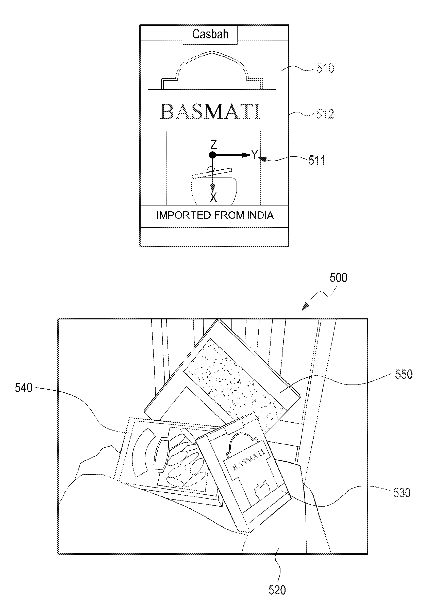
[0162]In FIG. 10A, a pose 533 of a first box 530 recognized by the image analysis module 220 is expressed by a three dimensional Cartesian coordinate system. In the first composition area 610 configured by the crop processing module 230, the first box 530 is biased to the left side.

[0163]Referring to FIG. 10B, the post processing module 240 detects that the pose 533 of the first box 530 is not the frontward pose (i.e. the reference pose 511 shown in FIG. 8A), and can move the first composition area 610 or flip over the left and right of the first composition area 610 (operation 611 as shown by the arrow in FIG. 10B) in a direction opposite to the direction in which the first box 530 is oriented (or in a direction in which the first box 530 is inclined) to modify the first composition area 610 into the second composition area 620. In the present embodiment, the...

second embodiment

[0166]FIGS. 11A and 11B are diagrams for describing post processing of a composition area according to the present invention.

[0167]Referring to FIG. 11A, the image analysis module 220 detects a contour line 531 and other feature points 532 of the first box 530, determines whether the detected contour line 531 and feature points 532 match with the feature points of the subject image 510, and determines that the first box 530 is identical to the registered subject image 510 when they match with each other. Further, without referring to the target database 212, the image analysis module 220 recognizes the second and the third boxes 540 and 550 defined by the edge feature points and the corner feature points in the input image 500. For example, the first box 530 may be recognized by the object recognition engine 420, and the second and third boxes 540 and 550 may be recognized by the line recognition engine 450.

[0168]In FIG. 11A, the detected contour lines 541 and 551 of the second and ...

third embodiment

[0173]FIG. 13 is a diagram for describing post processing of a composition area according to the present invention. The post processing module 240 can reconfigure a second composition area 725, 735, 745, or 755 by moving a first composition area 715 configured by the crop processing module 230 in a direction of line-of-sight according to a pose of a recognized face.

[0174]When the line-of-sight of a user is oriented frontward (as shown in box 710), the first composition area 715 configured by the crop processing module 230 is maintained without change by the post processing module 240. When the line-of-sight of a user is oriented upward (as shown in box 720), the first composition area 720 configured by the crop processing module 230 is moved upward to be reconfigured into the second composition area 725. When the line-of-sight of a user is oriented downward (as shown in box 730), the first composition area 715 configured by the crop processing module 230 is moved downward to be reco...


PUM


Abstract

An image editing method includes recognizing a subject in an input image and extracting information related to the recognized subject; identifying composition information corresponding to the extracted subject-related information in a composition database; configuring a composition area in the input image according to the identified composition information; and displaying an image corresponding to the composition area on a screen.

Description

PRIORITY[0001]This application claims priority under 35 U.S.C. §119(a) to Korean Application Serial No. 10-2013-0027278, which was filed in the Korean Intellectual Property Office on Mar. 14, 2013, the entire content of which is incorporated herein by reference.BACKGROUND[0002]1. Field of the Invention[0003]The present invention generally relates to an image editing method, and more particularly, to a method of editing an image based on a composition of a subject.[0004]2. Description of the Related Art[0005]An electronic device directly controlled by a user includes at least one display device, and the user can control the electronic device through an input device while viewing various operation states or application operations of the electronic device through the display device. In particular, a portable terminal, such as a mobile phone, which can be carried by a user, is typically not equipped, due to its limited size, with a four directional button for operation of up-down and le...

Claims


Application Information

Patent Timeline
IPC IPC(8): G06T3/40G06V10/44G06V10/56
CPCG06T3/40G06T11/60G06T2210/22G06V40/165G06V40/103G06V30/142G06V10/44G06V10/462G06V10/56G06T3/00G06T7/00G06T11/00
Inventor CHOE, JI-HWANCHOE, SEUNG-JOOCHO, SUNG-DAE
Owner SAMSUNG ELECTRONICS CO LTD
Why Eureka
Try Eureka