Multi-component lifting assembly for a container

a multi-component, container technology, applied in transportation and packaging, locomotives, borehole/well accessories, etc., can solve the problems of reducing the usable width and height of the interior container, and reducing the number of roof edges. , the effect of reducing the initial installation cost and repair cos

Inactive Publication Date: 2002-01-15
WABASH NAT SERVICES +1
View PDF14 Cites 20 Cited by
  • Summary
  • Abstract
  • Description
  • Claims
  • Application Information

AI Technical Summary

Benefits of technology

An object of the present invention is to provide a novel multi-component lifting assembly for a stackable and liftable container which allows the roof of the container to be installed in one piece and reduces the number of roof edges.
Another object of the present invention is to provide a novel multi-component lifting assembly for a stackable and liftable container which is designed to provide the ability to lift the container by top bayonet lifting and to lift the container by side lifting by pins in a convenient and easy manner.
A further object of the present invention to provide a novel multi-component lifting assembly for a stackable and liftable container which has reduced initial installation costs and repair costs versus the prior art.
Yet a further object of the present invention is to provide a novel multi-component lifting assembly for a stackable and liftable container which reduces the possibility of leaking versus the prior art.

Problems solved by technology

Typically, the castings and the frame protrude into the interior of the container and reduce the usable width and height on the interior of the container.
Additionally, the stacking frame disrupts the roof of the container causing the roof to be installed in three sections.
This results in four additional edges which are capable of leaking when raining.
The corners of the roof sections are also subject to fatigue.
In addition, prior art lifting mechanisms were designed for top bayonet lifting or side lifting by pins, but not both.

Method used


Image

  • Multi-component lifting assembly for a container
  • Multi-component lifting assembly for a container
  • Multi-component lifting assembly for a container

Examples


Embodiment Construction

While the invention may be susceptible to embodiment in different forms, there is shown in the drawings, and herein will be described in detail, a specific embodiment with the understanding that the present disclosure is to be considered an exemplification of the principles of the invention, and is not intended to limit the invention to that as illustrated and described herein.

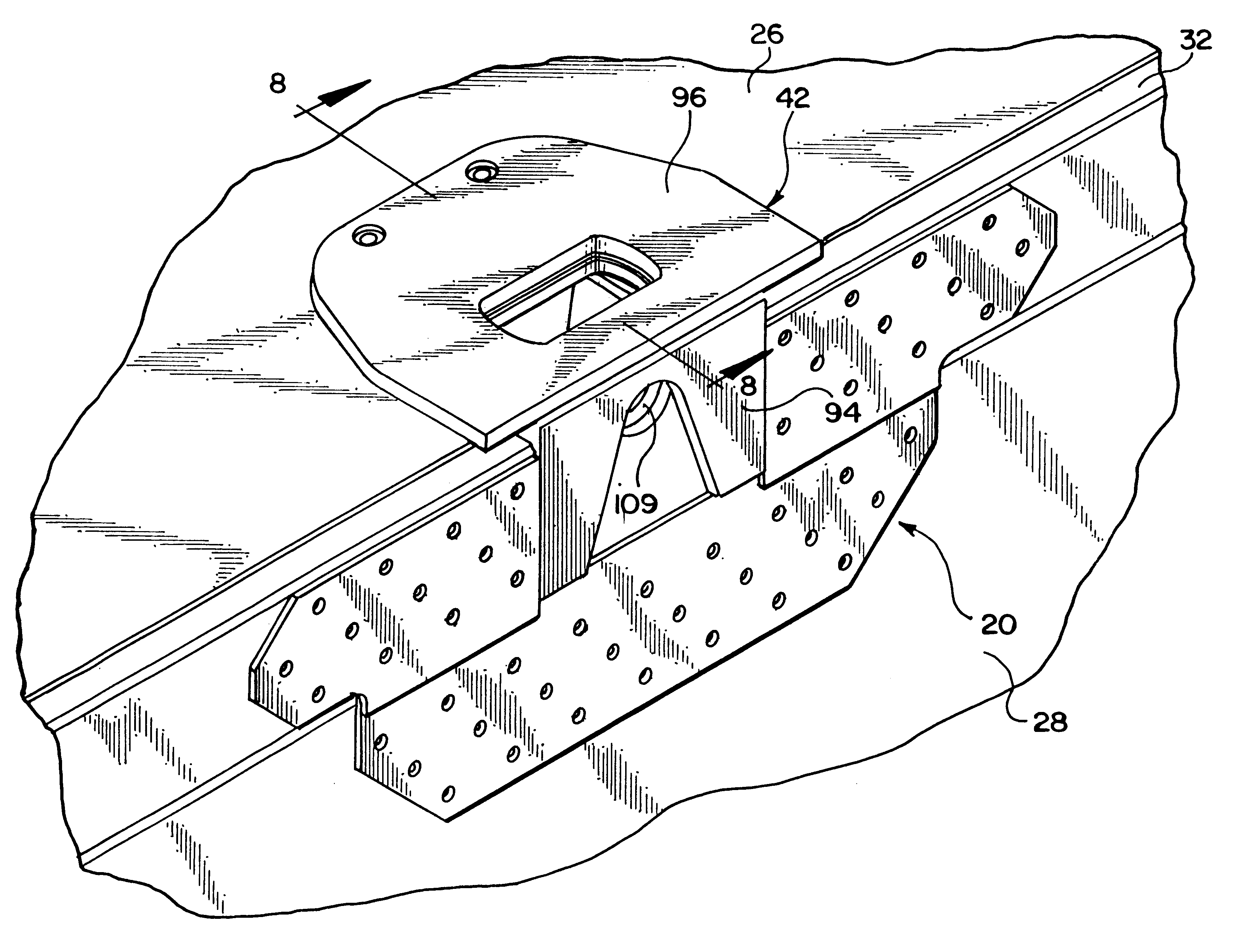
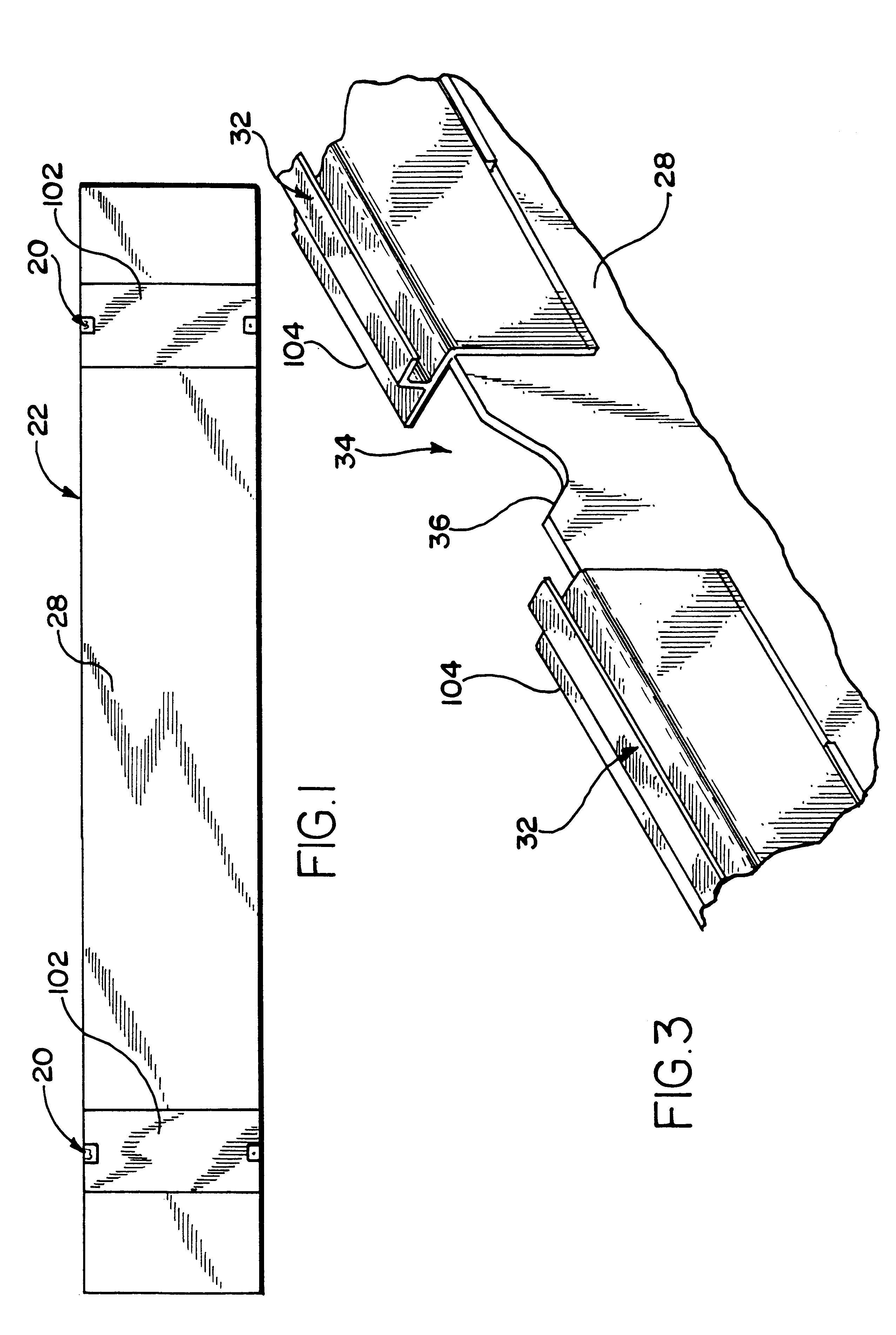
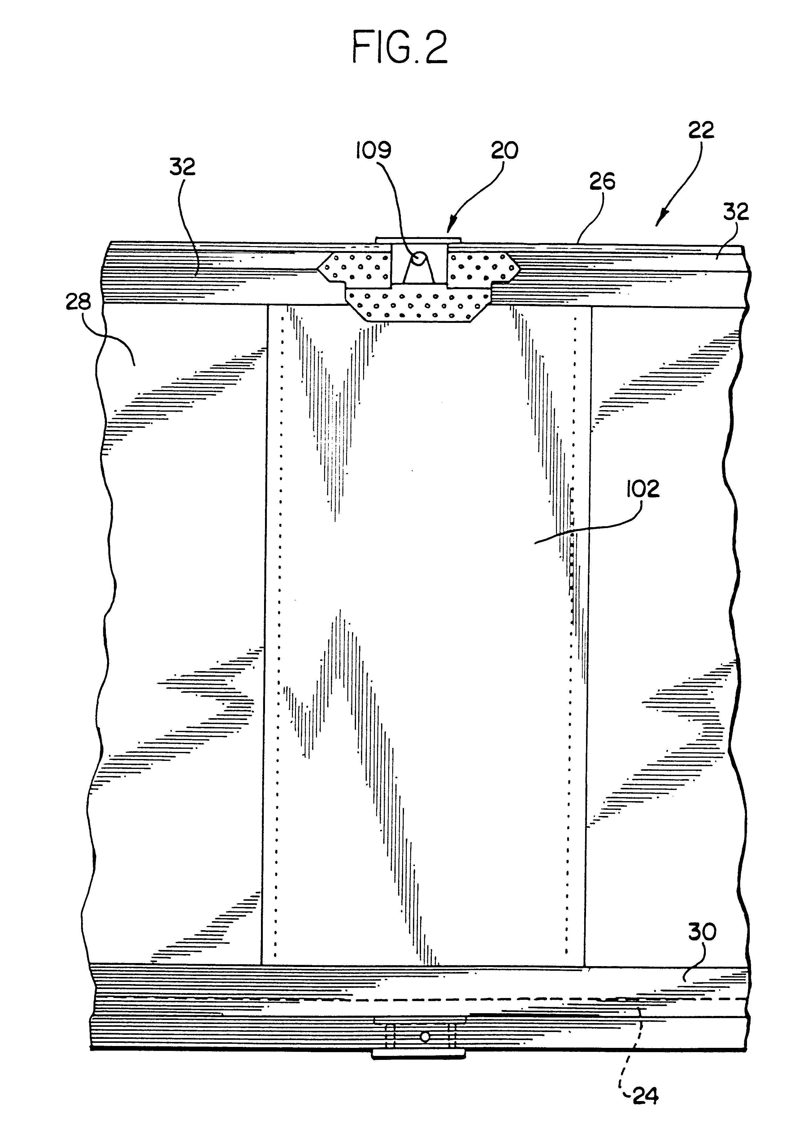
The present invention provides a novel multi-component lifting assembly 20 which is used on a stackable and liftable container 22. The container 22 includes a floor 24, a roof sheet 26, a front wall, a pair of opposite side walls 28 (only one of which is shown) and rear cargo doors. The container 22 is suitable for mounting on a conventional I-beam chassis trailer (not shown) which is towed by a conventional tractor (not shown). The container 22 of the present invention is greater than forty feet long, and is preferably fifty three feet long, and has a height of nine and a half feet.

Each side wall 28 of the co...


PUM


Abstract

A multi-component lifting assembly is provided for a container which carries cargo. The container includes a floor, opposite side walls extending upwardly from the floor, and a roof sheet attached to upper ends of the side walls. The lifting assembly is attached to the walls and to the roof sheet such that four-point lifting stability is provided when the container is lifted by an overhead crane. The lifting assembly includes a stacking header which spans the width of the container, an inner cap which is provided on an interior of the container, and an outer cap which is provided on the exterior of the container. The roof sheet is sandwiched between the outer cap and the stacking header. The side wall is sandwiched between the outer cap and the inner cap. Aligned apertures are provided through the outer cap, the roof sheet, the stacking header and the inner cap such that a bayonet can be inserted therein and the container can be lifted. Aligned apertures are provided through the outer cap, the side wall, and the inner cap such that a side lifting pin can be inserted therein and the container can be lifted.

Description

This invention is generally directed to a novel multi-component lifting assembly for a stackable and liftable container.Conventional stackable and liftable containers have side walls formed from a plurality of metal plates joined together by vertical metal posts and have a "top pick point" at the junction between the roof and the side wall of the container approximately forty feet apart from each along each side wall of the container. The top pick points are paired in alignment across the roof and are secured to respective top rails of the container. This provides for four-point lifting stability when the container is lifted by an overhead crane.A stacking frame is provided at these points. The stacking frame has aperture castings at the frame corners for connection during lifting and stacking. These castings are rectangular blocks with perpendicular edges. Typically, the castings and the frame protrude into the interior of the container and reduce the usable width and height on the...

Claims


Application Information

Patent Timeline
Patent Type & Authority Patents(United States)
IPC IPC(8): B65D90/00
CPCB65D90/0033B65D90/0026
Inventor WILLIAMS, DEWAYNE B.
Owner WABASH NAT SERVICES
Why Eureka
Try Eureka