
Projector apparatus

a projector and apparatus technology, applied in the direction of color signal processing circuits, printers, camera focusing arrangement, etc., can solve the problems of complex and troublesome adjustment of color temperature and/or white balance on the screen, deformation of the apparatus body, etc., and achieve the effect of simple and convenient adjustmen

Active Publication Date: 2006-07-04
D & M HOLDINGS INC
View PDF9 Cites 18 Cited by
  • Summary
  • Abstract
  • Description
  • Claims
  • Application Information

AI Technical Summary

Benefits of technology

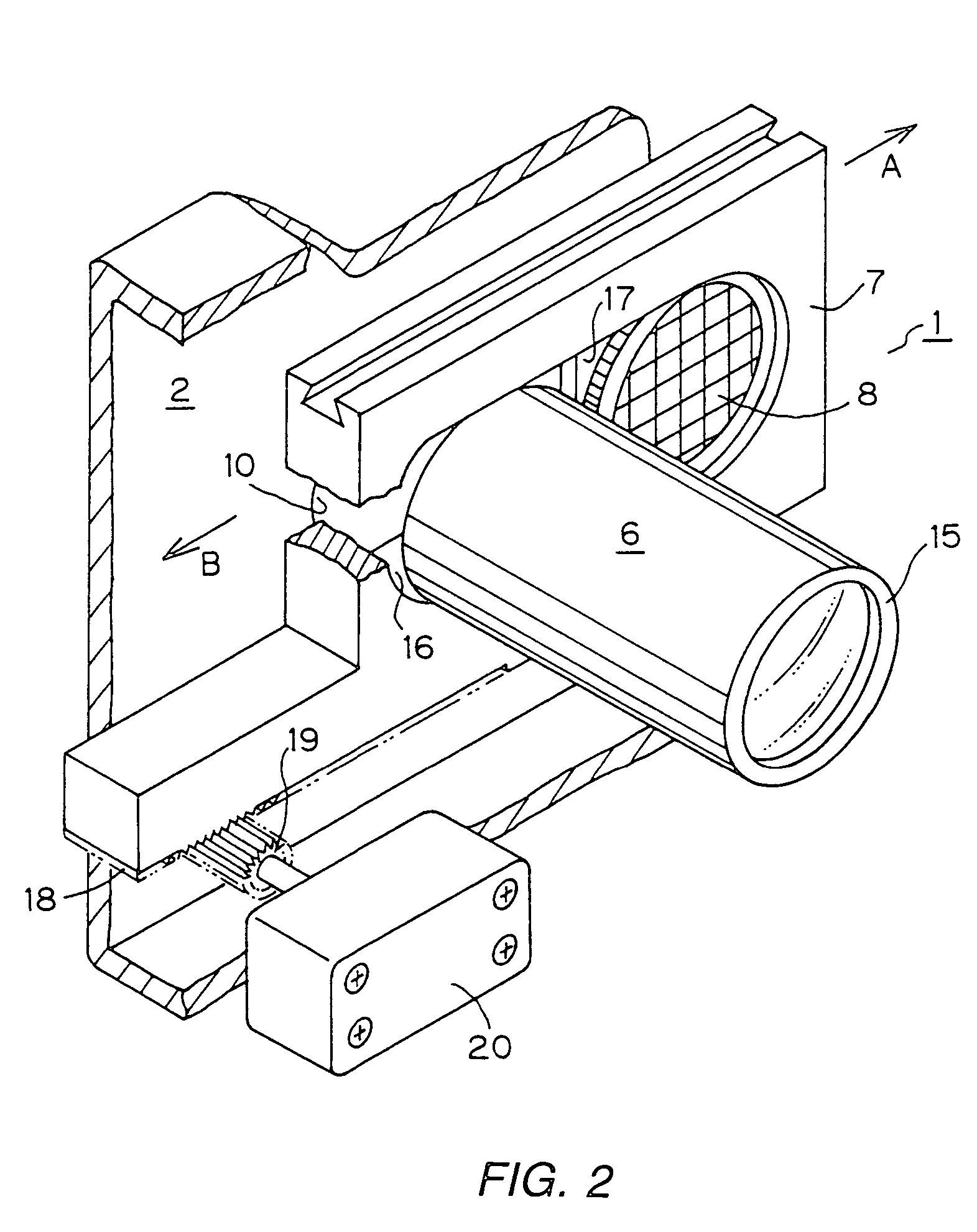
The present invention provides a projector apparatus that can easily and accurately detect and adjust the color temperature and white balance of the projection light, even when the projection optics is slid relative to the apparatus body. This is achieved by a shutter disposed downstream of the projection optics means and a sensor means attached to the shutter for detecting the color temperature of the light for projection. The control means can adjust the color temperature to a desired value, regardless of changes in the apparatus body or the components. The sliding means allows for the sensor to follow the projection optics means and detect the color temperature from the sliding position. The invention provides a simple and convenient solution for adjusting the color temperature and white balance of the projection light.

Problems solved by technology

The generated heat may bring about a change in temperature in the body of the apparatus, leading to deformation of the apparatus body.
Thus, the DLP-type projector apparatus has a problem that the color temperature and the white balance, which represent the quality of the projection light in terms of perceived colors of image, may change whereby the predefined colors are not maintained, with the result that images cannot be obtained with the colors originally intended.
In actuality, however, the screen on which an image is formed by the projected light and the projector apparatus are a large distance apart from each other, which causes another problem that it is necessary to provide a means of a considerable scale for feeding the sensing results back to projector apparatus.
Also, the sensing of the color temperature and / or white balance of the projection light in the DLP-type projector apparatus should be done exclusively for the projection light and thus need be performed in a condition where no other lights exist, which makes the work necessary for sensing the color temperature and / or white balance on the screen and for adjusting them very complicated and troublesome and thus renders the problem more serious.
Hence, the detection of the color temperature of the projection light and the adjustment of the color temperature based on the detection results are carried out in a dark condition, which makes the work necessary therefor very complicated and troublesome and thus renders the problem more serious.
This structure makes it possible to carry out the detection of the color temperature and / or white balance of the light within the apparatus body and can thus circumvent the problem that the means necessary for adjusting the color temperature and / or while balance of the projection light becomes large in scale as well as the problem that the work itself for carrying out the detection of the color temperature and / or white balance is troublesome.
Therefore, the projector apparatus of this structure has a problem that accurate sensing and secure adjustment of the color temperature and / or white balance cannot be achieved.
If a picture whose color temperature and white balance are not accurately maintained is recognized as a picture whose color temperature and white balance are properly maintained, the value of the picture work itself projected by that projector apparatus will be harmed, which will render the problem more serious.

Method used


Image

  • Projector apparatus
  • Projector apparatus
  • Projector apparatus

Examples


Embodiment Construction

[0031]Hereunder, the present invention according to a first aspect will be described with reference to the embodiment shown in the figures. It should however be noted that the present invention is not restricted to this embodiment.

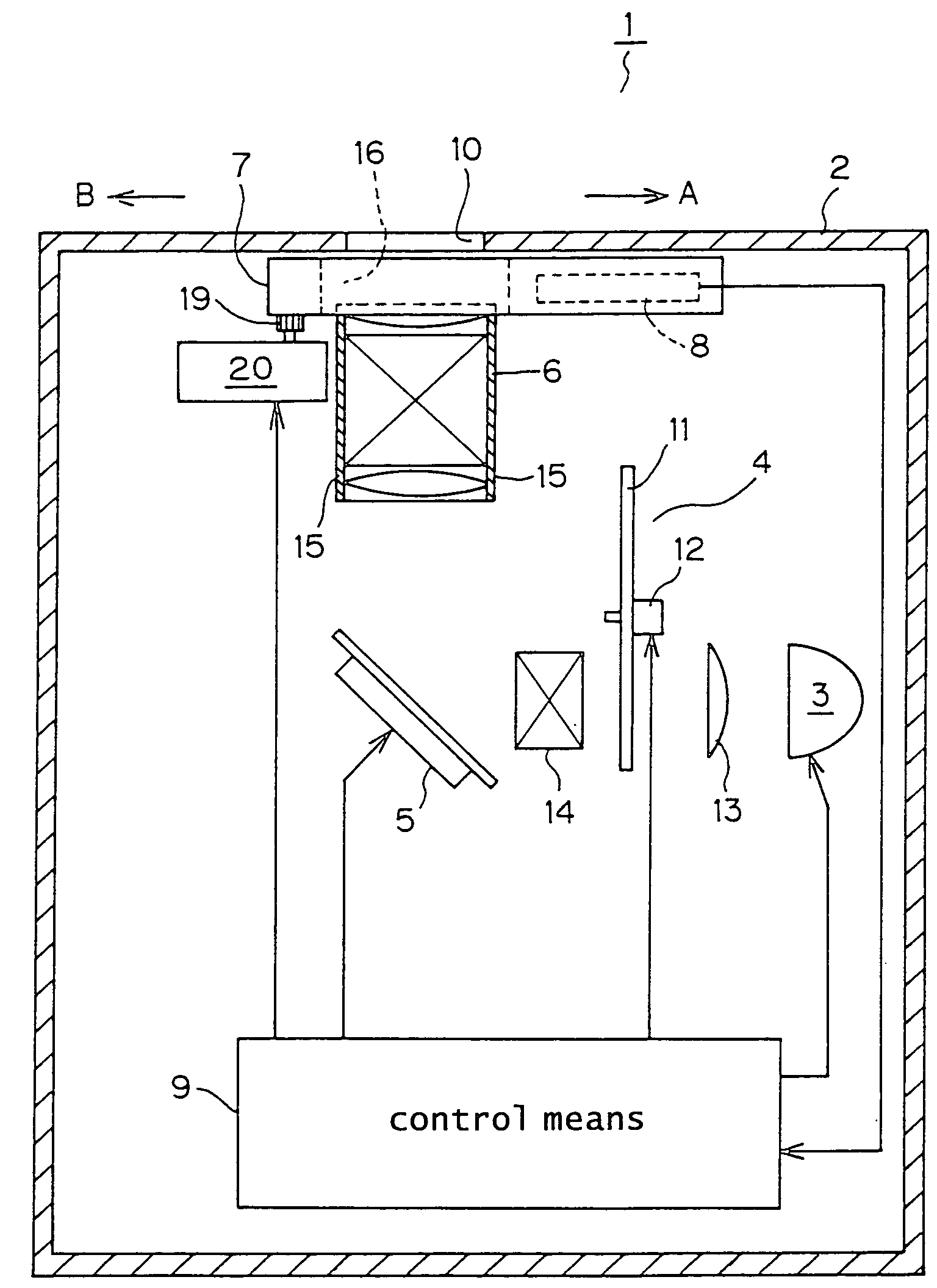
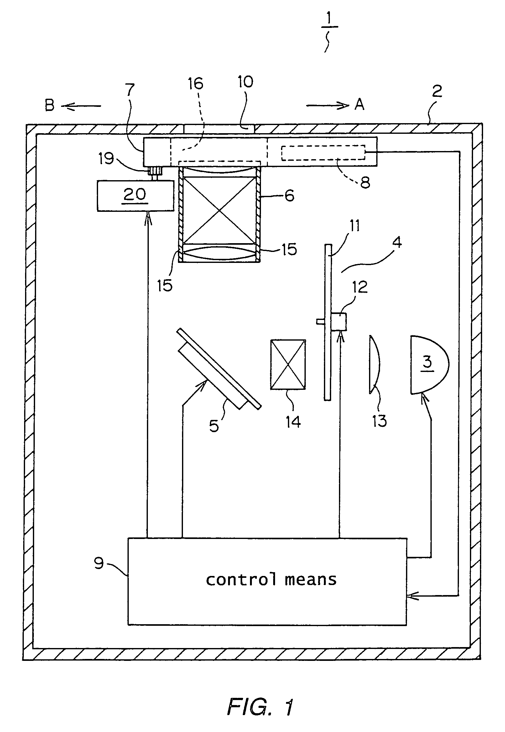
[0032]As shown in FIG. 1, a projector apparatus 1 according to this invention comprises a casing 2, a light source means 3, a color wheel means 4, a DMD section 5, a projection optics 6, a shutter 7, a sensor means 8 and a control means 9.

[0033]The casing 2 is formed in its front wall with an opening 10 for passing the projection light from the projection optics 6. The light source means 3 is provided for supplying a white light and is controlled by the control means 9 such that the supply of the white light is switched on or off.

[0034]The color wheel means 4 is arranged to receive the light from the light source 3 and to output a plurality of primary-color lights. The color wheel means 4 is constituted mainly by a disc-like color filter 11 divided circumf...


PUM

PropertyMeasurementUnit
sizeaaaaaaaaaa
color temperatureaaaaaaaaaa
temperatureaaaaaaaaaa

Abstract

A projector apparatus includes digital micromirror device (DMD) Color temperature and adjustment of white balance with respect to projection light can be detected in a light condition in a convenient manner. A position of the picture formed by the projection light on the screen can be shifted. A projector apparatus includes a shutter disposed downstream of the projection optics for blocking the projection light and a sensor attached to the shutter. In a second embodiment, a projector apparatus includes a sliding structure for causing a projection optics to be slid relative to a casing constituting an apparatus body in a perpendicular relation to the optical axis of projection optics means and a follow-up structure for causing a sensor to follow the projection optics means.

Description

BACKGROUND OF THE INVENTION[0001]1. Field of the Invention[0002]The present invention relates to a projector apparatus for projecting a projection light obtained by passing a white light from a light source through a color splitting device or a color wheel means, Digital Micromirror Device™ (hereinafter referred to as “DMD™”) and an optical means for projection onto a screen to form thereon a desired picture, that is to say, a projector apparatus of the so-called Digital Light Processing™ type (hereinafter referred to as “DLP™ type”).[0003]More particularly, the present invention relates to a projector apparatus in which color adjustments of the projection light such as an adjustment of the color temperature and an adjustment of the white balance can be achieved more easily and accurately.[0004]2. Prior Art[0005]It is very important for a projector apparatus of the DLP type to have the desired color temperature and white balance which represent the quality of the projection light. W...

Claims


Application Information

Patent Timeline
Patent Type & Authority Patents(United States)
IPC IPC(8): G03B21/14G02F1/00G03B21/28G03B3/00H04N5/74H04N9/12H04N9/73H04N9/31
CPCG03B21/14H04N5/7458H04N9/73H04N9/3197H04N9/3114G03B21/008G03B21/145
Inventor TANAKA, NOBUTOMOKAMINO, EIICHI
Owner D & M HOLDINGS INC
Learn More