Method and apparatus for video surveillance

a video surveillance and video technology, applied in the field of video surveillance, can solve the problems of low-level detection and tracking algorithms that do not adapt well to different imagers, still exhibit a relatively high false alarm rate, and high false alarm ra

Inactive Publication Date: 2007-02-15
SARNOFF CORP
View PDF2 Cites 79 Cited by
  • Summary
  • Abstract
  • Description
  • Claims
  • Application Information

AI Technical Summary

Problems solved by technology

While such systems provide improved performance over earlier pixel-change detection systems, they still tend to exhibit a relatively high false alarm rate.
The high false alarm rate is due, in part, to the fact that low-level detection and tracking algorithms do not adapt well to different imager and scene conditions (e.g., the same tracking rules apply in, say, an airport and a sea...

Method used


Image

  • Method and apparatus for video surveillance
  • Method and apparatus for video surveillance
  • Method and apparatus for video surveillance

Examples


Embodiment Construction

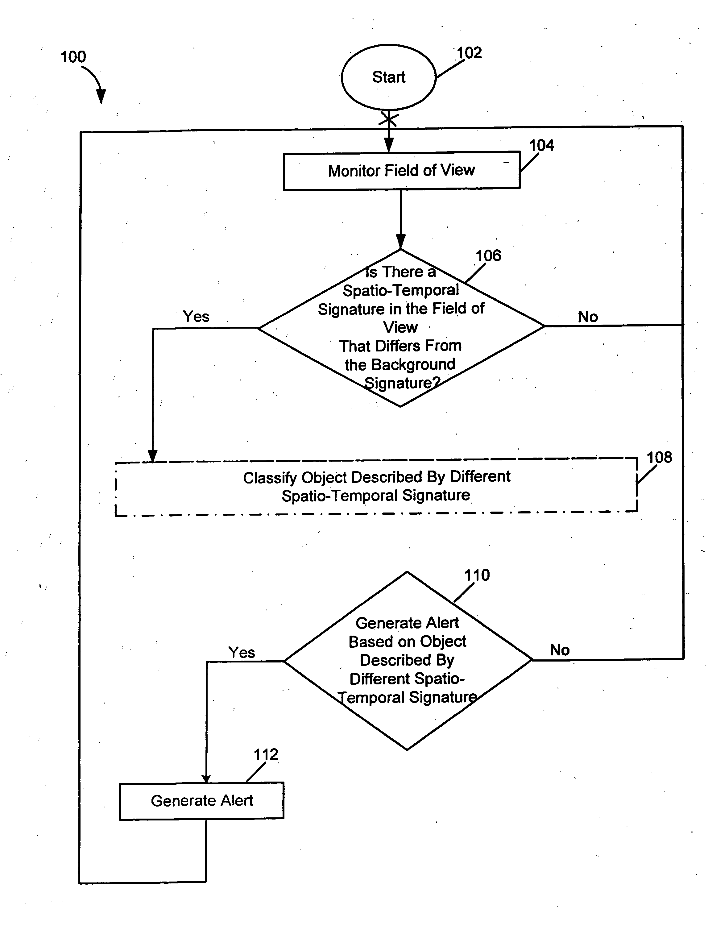
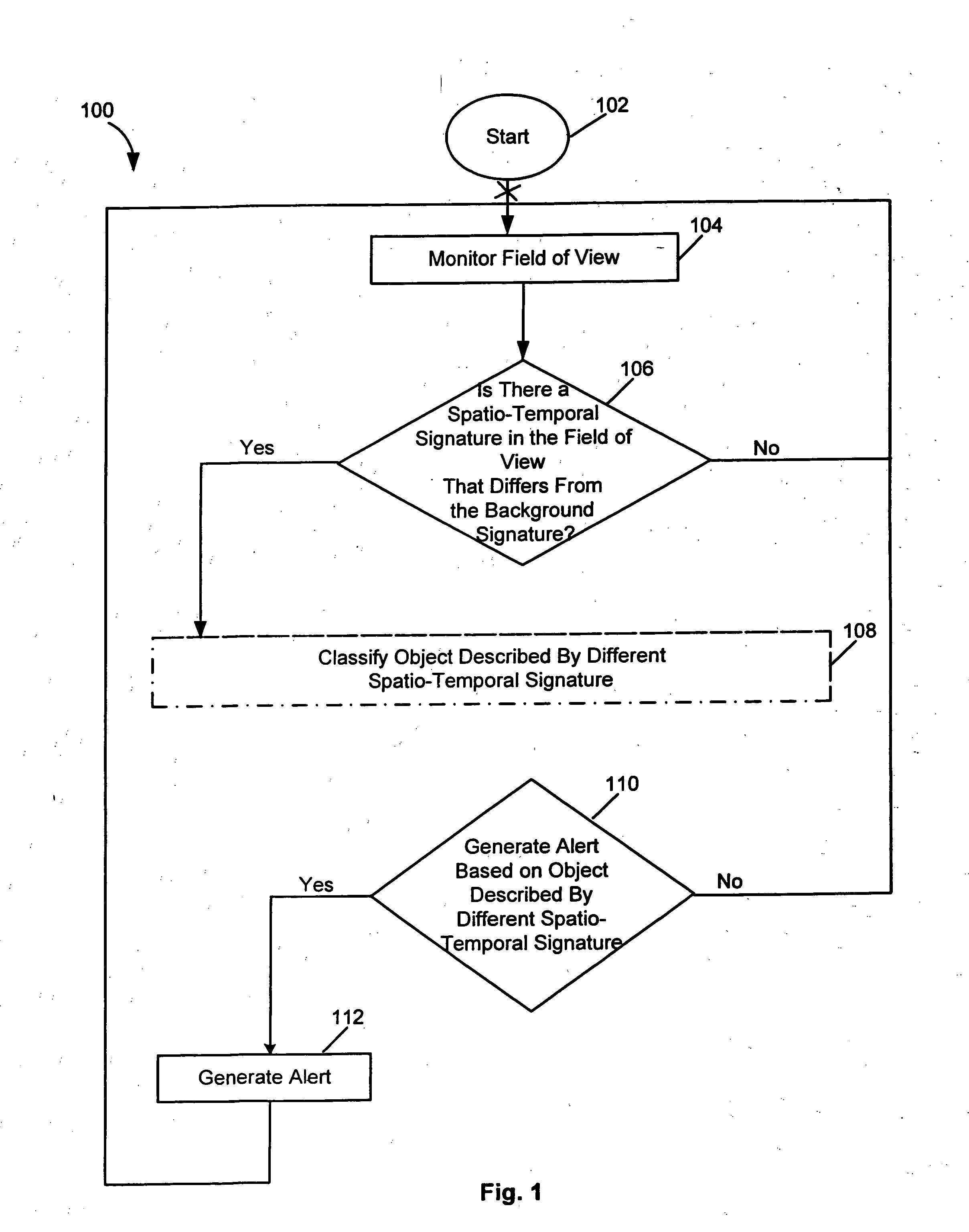
[0011] The present invention discloses a method and apparatus for providing improved surveillance and motion detection by defining a moving object according to a plurality of feature vectors, rather than according to just a single feature vector. The plurality of feature vectors provides a richer set of information upon which to analyze and characterize detected motion, thereby improving the accuracy of surveillance methods and substantially reducing false alarm rates (e.g., triggered by environmental movement such as swaying trees, wind, etc. and other normal, real world events for which existing surveillance systems do not account).

[0012]FIG. 1 is a flow diagram illustrating one embodiment of a method 100 for video surveillance, according to the present invention. The method 100 may be implemented, for example, in a surveillance system that includes one or more image capturing devices (e.g., video cameras) positioned to monitor a field of view. For example, one embodiment of a mo...


PUM


Abstract

A method and apparatus for performing video surveillance of a field of view is disclosed. In one embodiment, a method for performing surveillance of the field of view includes monitoring the field of view and detecting a moving object in the field of view, where the motion is detected based on a spatio-temporal signature (e.g., a set of descriptive feature vectors) of the moving object.

Description

CROSS-REFERENCE TO RELATED APPLICATIONS [0001] This application claims benefit of U.S. provisional patent application Ser. No. 60 / 575,974, filed Jun. 1, 2004, which is herein incorporated by reference in its entirety.BACKGROUND OF THE INVENTION [0002] The need for effective surveillance and security at airports, nuclear power plants and other secure locations is more pressing than ever. Organizations responsible for conducting such surveillance typically deploy a plurality of sensors (e.g., video and infrared cameras, radars, etc.) to provide physical security and wide-area awareness. For example, across the United States, an estimated nine million video security cameras are in use. [0003] Typical vision-based surveillance systems depend on low-level video tracking as a means of alerting an operator to an event. If detected motion (e.g., as defined by flow) exceeds a predefined threshold, an alarm is generated. While such systems provide improved performance over earlier pixel-chang...

Claims


Application Information

Patent Timeline
IPC IPC(8): H04N7/18H04N5/225
CPCG06K9/00771G06T7/20G08B13/19602H04N7/188G08B13/19613H04N5/144G08B13/19606G06V20/52
Inventor HANNA, KEITH J.AGGARWAL, MANOJSAWHNEY, HARPREET
Owner SARNOFF CORP
Why Eureka
Try Eureka