Adjustably fitted protective apparel with rotary tension adjuster

a technology of tension adjustment and adjustable fit, which is applied in the direction of protective clothing, protective garments, protective equipments, etc., can solve the problems of cumbersome loosening of vests into loose fitting dispositions, degrading the protection of vests, and cumbersome loosening of vests, so as to prevent bunching, gathering or migration

Inactive Publication Date: 2007-02-22
ENVENTYS
View PDF65 Cites 25 Cited by
  • Summary
  • Abstract
  • Description
  • Claims
  • Application Information

AI Technical Summary

Benefits of technology

[0033] In still another feature, the first tensioning line extends from the rotary tension adjuster to a side portion of the vest and is connected to an elastic cord that passes freely through loops respectively attached to the front and rear side portions of the vest,

Problems solved by technology

The protection afforded by the vest may be degraded if the vest is worn in a loose fit permitting play between the vest and the body.
On the other hand, a snug fit may be less comfortable than a loose fit, and a wearer may prefer the ability to alternate between a loose fit and a snug fit depending on the currently perceived threat level.
Unfortunately, it ca

Method used


Image

  • Adjustably fitted protective apparel with rotary tension adjuster
  • Adjustably fitted protective apparel with rotary tension adjuster
  • Adjustably fitted protective apparel with rotary tension adjuster

Examples


first embodiment

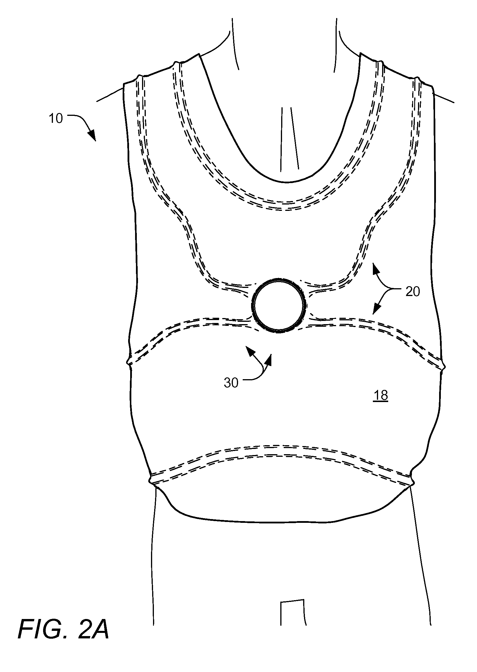
[0062]FIG. 2A is a front view of an article of adjustably fitted protective apparel 10, worn by a user, according to the present invention; FIG. 2B is a front view of the article of protective apparel 10 of FIG. 2A, still worn by a user, but shown with an outer cover 18 removed for clarity; FIG. 2C is a front view of the article of protective apparel 10 of FIG. 2A, shown in an unworn disposition; and FIG. 3A is a side cross-sectional view of a portion of the right side of the article of protective apparel 10 of FIG. 2C, taken along line 3-3. As collectively shown therein, the illustrated article 10, often generally referred to hereinafter as a bullet-proof vest, comprises one or more protective panels 12, an inner cover 14, a middle cover 16, an outer cover 18, a channel distribution system 20 and an adjustable tensioning system 30.

[0063] The adjustable tensioning system 30 comprises a rotary tension adjuster 32 and a plurality of tensioning lines 34, 36, while the channel distribut...

third embodiment

[0083]FIGS. 5A and 5B are front views of an article of adjustably fitted protective apparel 210 according to the present invention, and FIG. 6 is a front view of the article of adjustably fitted protective apparel 210 of FIG. 5A. In this embodiment, four tension loops 234 extend from a rotary tension adjuster 232 centrally located at the sternum area of the front of the vest. Each loop 234 extends from the rotary tension adjuster 232 and through a respective clip 237. The clips 237 are each removably attached to holed bands 239 attached to the vest 210. Respective left and right yoke bands 239 extend from the front pectoral areas to the back shoulder blade areas of the vest 210. As shown in FIG. 6, a single waist band 239 passes across the lower portion of the back of the vest 210 and has respective opposite ends that extend beneath the arms along the ribs toward the adjuster 232. Each band 239 provides a number of holes 241 for receiving a clip 237 so that positioning each clip 237...

fourth embodiment

[0084]FIG. 7 is a front view of an article of adjustably fitted protective apparel 310 according to the present invention. In this embodiment, a receiving pocket 250 is formed in the article for receiving a tension adjuster. One or more apertures are defined in the pocket for extension there through of control elements of a tension adjuster so that the tension adjuster can be manipulated without removal from the pocket. Furthermore, in this embodiment, yoke portions of the article comprise crossed belts, for example woven nylon belts, that provide strength and that are covered by fabric portions for comfort.


PUM


Abstract

An article of adjustably fitted protective apparel includes a vest and an adjustable tensioning system for selective tensioning of the vest into a snug fit on a body of a wearer of the vest. The adjustable tensioning system includes a rotary tension adjuster disposed on the vest and including a housing and a first spool disposed within the housing, and a tensioning line extends from the housing. The tensioning line is attached directly or indirectly to the vest. A portion of the tensioning line is configured to be wound upon the first spool during manipulation of the rotary tension adjuster in a first rotational direction thereof. Winding of the portion of the first tensioning line draws together first portions of the vest for providing a snug fit of the first portions.

Description

I. CROSS-REFERENCE TO RELATED APPLICATIONS [0001] This application is a continuation of, and claims priority under 35 U.S.C. § 120 to, U.S. patent application Ser. No. 11 / 276,400, filed Feb. 27, 2006, which published as U.S. Patent Application Publication No. US 2006 / ______ , which is a nonprovisional of, and claims priority under 35 U.S.C. § 119(e) to, U.S. Provisional Patent Application No. 60 / 656,335, filed Feb. 25, 2005, and which is a continuation-in-part of: (1) U.S. patent application Ser. No. 11 / 276,357, filed Feb. 24, 2006, which published as U.S. Patent Application Publication No. US 2006 / ______, and which is a continuation-in-part of each of (A) U.S. patent application Ser. No. 11 / 222,549, filed Sep. 9, 2005, which is a continuation-in-part of U.S. patent application Ser. No. 11 / 123,942, filed May 6, 2005, which published as U.S. Patent Application Publication No. US 2006 / 0015988 A1, and which is a nonprovisional of 60 / 569,304, 60 / 608,397, and 60 / 656,335, and (B) U.S. pat...

Claims


Application Information

Patent Timeline
IPC IPC(8): A42B1/04A61F9/02
CPCF41H1/02A41D15/00
Inventor KOVACEVICH, IAN D.DAHLQUIST, KEVIN J.PHILPOTT, TOMBIZZELL, DANIEL LEE
Owner ENVENTYS
Why Eureka
Try Eureka