Reflector, light source device and projection display apparatus

Inactive Publication Date: 2007-02-22
SHARP KK
View PDF9 Cites 24 Cited by
  • Summary
  • Abstract
  • Description
  • Claims
  • Application Information

AI Technical Summary

Benefits of technology

[0032] According to the present invention, it is possible for the light-to-heat converting means to absorb light in a wavelength range that passes through the specific wavelength range reflecting component and efficiently convert it into heat, and provision of the buffering component brings about the following effects.
[0033] (1) It is possible to suppress deformation of the heat radiating means occurring as a result of the generation of stress from heat due to the difference in thermal expansion arising at the joined interface between the light-to-heat converting component and the specific wavelength range reflecting component, whereby it is possible to prevent the phenomenon of the projected light from the light source not propagating straight.
[0034] (2) It is possible to alleviate the influence of jaggedness present in the light-to-heat converting component and smoothen the light source-side surface of the specific wavelength range reflecting component, whereby it is possible to p

Problems solved by technology

Since the metal halide lamp or high-pressure mercury lamp entails a high generation of heat, it is necessary to forcibly cool it down because the lamp itself reaches a high temperature during usage.
Specifically, if the lamp itself reaches a high temperature during usage, an excessive rise in temperature of the lamp body and the concave mirror for reflecting light from the lamp in a desired direction will take place, ca

Method used


Image

  • Reflector, light source device and projection display apparatus
  • Reflector, light source device and projection display apparatus
  • Reflector, light source device and projection display apparatus

Examples


Example

The First Embodiment

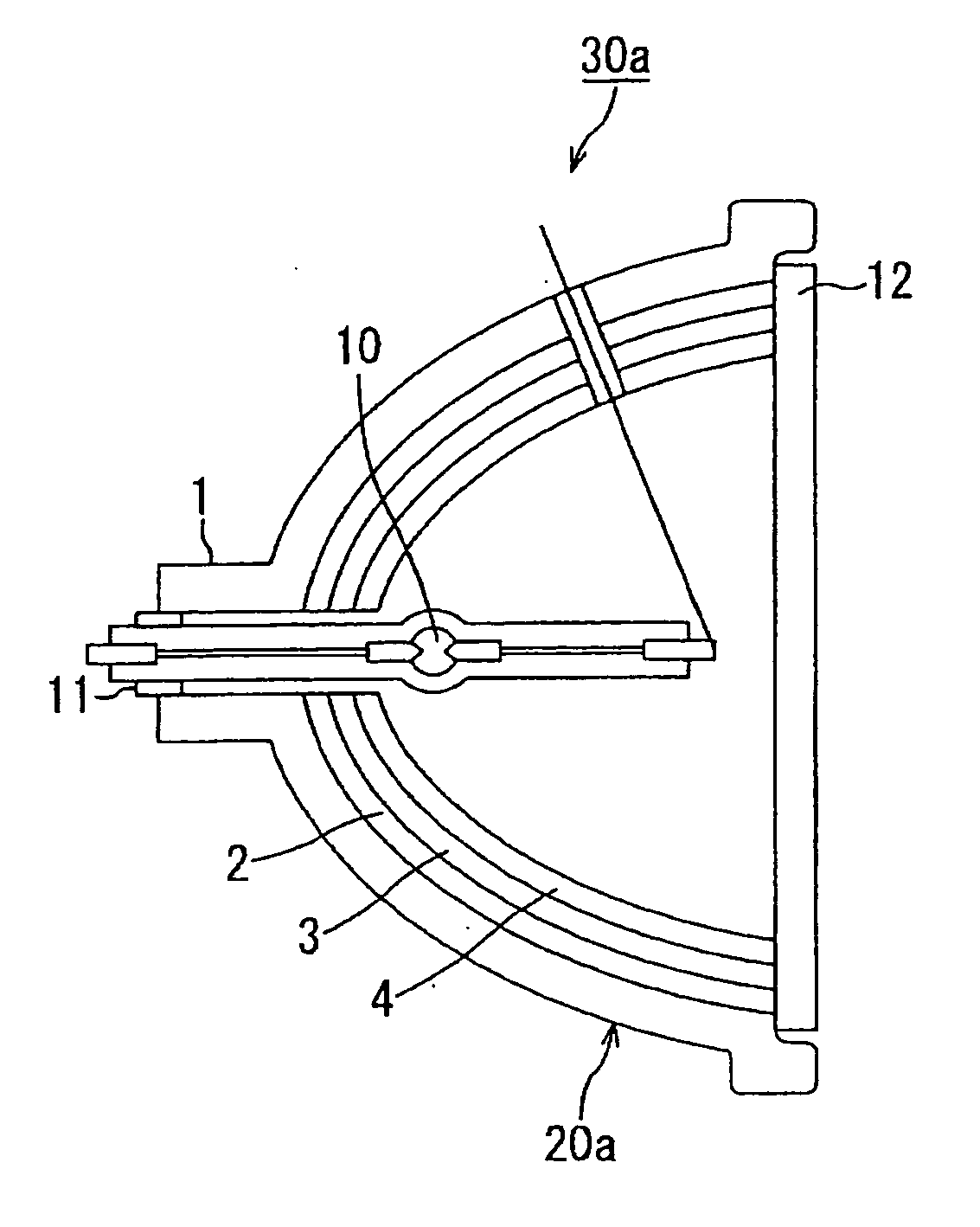
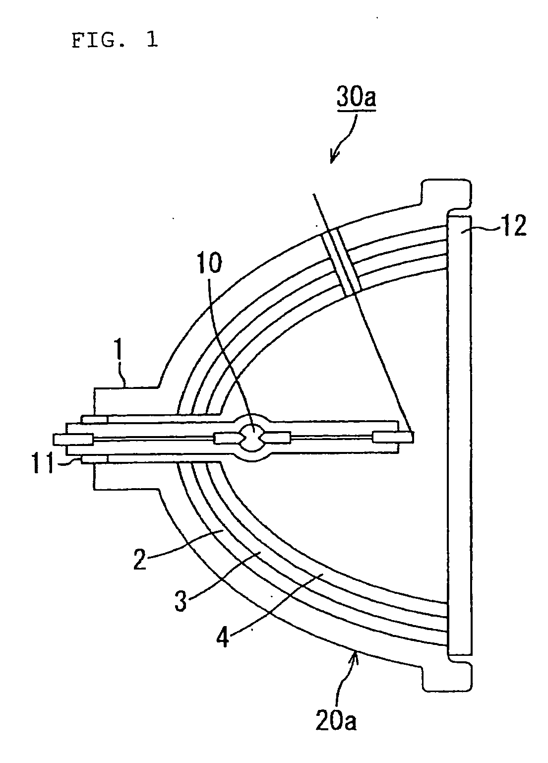
[0063]FIG. 1 is a configurational view showing an overall structure of a light source device including a reflector according to the first embodiment of the present invention. Here, the same components as in the conventional reflector shown in FIG. 6 are allotted with the same reference numerals.

[0064] In the figure, a light source device 30a according to the first embodiment of the present invention includes a light source 10 and a transparent explosion-proof glass 12, in addition to a reflector 20a. Reflector 20a is comprised of a concave mirror substrate (heat radiating means) 1, and an infrared-to-heat converting layer (light-to-heat converting component) 2, a gloss-forming buffer layer (buffering layer) 3 and a visible light reflecting layer (specific wavelength range reflecting component) 4, laminated on the mirror surface side (the light source-side surface) of concave mirror substrate 1.

[0065] Next, the detailed configurations and functions of the refle...

Example

The Second Embodiment

[0081]FIG. 3 is a configurational view showing a reflector structure according to the second embodiment of the present invention.

[0082] In the reflector 20a according to the first embodiment, concave mirror substrate 1, infrared-to-heat converting layer 2, gloss-forming buffer layer 3 and visible light reflecting layer 4 are provided with their layers joined in surface contact with one another. In a reflector 20b according to the present embodiment, the joined surfaces between the aforementioned layers are formed with projections and indentations, as sown in FIG. 3.

[0083] More specifically, projections and indentations are formed first on the surface of a concave mirror substrate 1b between concave mirror substrate 1b and an infrared-to-heat converting layer 2b.

[0084] Also, projections and indentations are formed on the surface of the infrared-to-heat converting layer 2b between the infrared-to-heat converting layer 2b and a gloss-forming buffer layer 3b.

[0...

Example

The Third Embodiment

[0087] The reflector structure according to the third embodiment of the present invention is the same reflector structure according to the first or second embodiment of the present invention, except in that the method of forming the constituents of infrared-to-heat converting layer 2 and gloss-forming buffer layer 3 and part of the structure are different. Hence, only the different points will be described in the description hereinbelow,

[0088] Infrared-to-heat converting layer 2 is formed by coating ceramic over concave mirror substrate 1 formed of aluminum and calcining these. That is, this calcination modifies the interface between concave mirror substrate 1 and the ceramic coating, producing a metal oxide layer. This metal oxide layer has the function of converting infrared rays to heat.

[0089] Gloss-forming buffer layer 3 is formed by ceramic coating.

[0090] Next, the reason for forming infrared-to-heat converting layer 2 by the above method will be describ...


PUM


Abstract

A concave mirror substance 1 constituting a reflector is composed of a base material having a high thermal conductivity such as aluminum etc. An infrared-to-heat converting layer 2 is film-formed by anodizing the substrate formed of aluminum etc., so as to absorb light in a wavelength range which passes through a visible light reflecting layer 4 and convert it into heat. A gloss-forming buffer layer 3 is film-formed by calcining Si resin or polyimide resin over the inner side (the light source-side surface) of infrared-to-heat converting layer 2 at high temperatures, so as to buffer the two layers in a manner that does not allow infrared-to-heat converting layer 2 and visible light reflecting layer 4 to be in direct contact with each other, and so as to reduce the influence of projections and indentations present on infrared-to-heat converting layer 2 and smoothen the light source-side surface of visible light reflecting layer 4. In this way, it is possible to suppress performance degradation by efficient discharge of heat by converting light into heat and by alleviating thermal stress and strain due to the difference in expansion coefficient between components, and it is also possible to achieve reduction in cost, miniaturization and weight reduction.

Description

TECHNICAL FIELD [0001] The present invention relates to a reflector for reflecting light emitted from a light source to a desired direction, a light source device having the reflector and a projection display apparatus including the light source device having the reflector. BACKGROUND ART [0002] Conventional projection display apparatuses use a metal halide lamp, high-pressure mercury lamp or the like as a high-intensity light source with a reflector that reflects light emitted from the light source to a desired direction. This reflector is mainly composed of a concave mirror having the function of reflecting light from the light source in a desired direction. [0003] Since the metal halide lamp or high-pressure mercury lamp entails a high generation of heat, it is necessary to forcibly cool it down because the lamp itself reaches a high temperature during usage. Specifically, if the lamp itself reaches a high temperature during usage, an excessive rise in temperature of the lamp bod...

Claims


Application Information

Patent Timeline
IPC IPC(8): F21V7/00G02B5/10F21S2/00F21V29/00F21Y101/00G02B5/08G03B21/00G03B21/14G03B21/16G03B21/20
CPCG03B21/16G03B21/2066G03B21/2086
Inventor SAITO, SAKAEKIKKAWA, ITSUROTAKEDA, AKINOBU
Owner SHARP KK
Why Eureka
Try Eureka