
Network physical connection inference for IP tunnels

a network physical connection and tunnel technology, applied in the field of network analysis, can solve the problems of fast rendering obsolete the defined topology, using dynamic routing, and modeling is the ip

Active Publication Date: 2007-02-22
RIVERBED TECH LLC
View PDF6 Cites 20 Cited by
  • Summary
  • Abstract
  • Description
  • Claims
  • Application Information

AI Technical Summary

Problems solved by technology

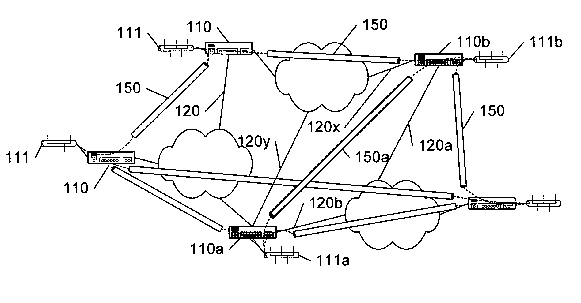
A common difficulty in network modeling is the modeling of IP tunnels, because the virtual private network is specifically provided to appear to be a local network, and the physical topology is masked.
Another difficulty associated with the modeling of IP tunnels is the use of dynamic routing, wherein the physical topology may change based on changing configurations, device faults, and so on.
Thus, even if a user defines the physical topology corresponding to an IP tunnel, dyamic routing may quickly render that defined topology obsolete.
Further compounding the difficulty of modeling IP tunnels is the use of dynamic tunnels wherein each tunnel is created on an ‘as needed’ basis.

Method used


Image

  • Network physical connection inference for IP tunnels
  • Network physical connection inference for IP tunnels
  • Network physical connection inference for IP tunnels

Examples


Embodiment Construction

[0022] In the following description, for purposes of explanation rather than limitation, specific details are set forth such as the particular architecture, interfaces, techniques, etc., in order to provide a thorough understanding of the concepts of the invention. However, it will be apparent to those skilled in the art that the present invention may be practiced in other embodiments, which depart from these specific details. In like manner, the text of this description is directed to the example embodiments as illustrated in the Figures, and is not intended to limit the claimed invention beyond the limits expressly included in the claims. For purposes of simplicity and clarity, detailed descriptions of well-known devices, circuits, and methods are omitted so as not to obscure the description of the present invention with unnecessary detail.

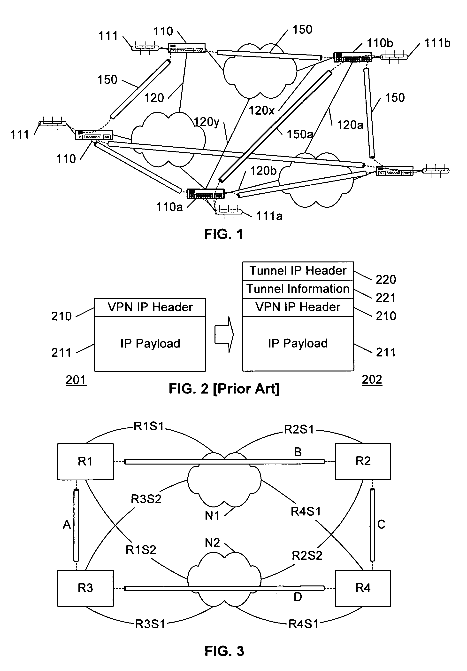
[0023]FIG. 3 illustrates an example network of four routers R1-R4 with physical R1S1-R4S4 and virtual A-D connections among these routers. In ...


PUM


Abstract

The physical connection corresponding to IP tunnels in a network are found by tracing through the device configuration and routing tables at the routers in the network to determine the outbound interface associated with each tunnel endpoint, and then inferring a likely return interface associated with the opposite tunnel endpoint. Depending upon the particular configurations, a variety of tests can be applied to validate the inference. Patricia trees are preferably used to store and process the configuration data for efficient tracing through the routing tables at each router.

Description

[0001] This application claims the benefit of U.S. Provisional Patent Application 60 / 709,769, filed 19 Aug. 2006.BACKGROUND AND SUMMARY OF THE INVENTION [0002] This invention relates to the field of network analysis, and in particular to network modeling. [0003] The management of a complex network requires the use of tools that facilitate the analysis and diagnosis of network performance, and tools have been developed to ease this task. Many of the tools that have been developed for such analysis and diagnosis employ models of the networks to emulate / simulate the actual operations that occur within the network, or to predict performance parameters related to the expected performance of the network under a variety of conditions. [0004] In order to effectively model the performance of a network, it is often necessary to model the physical topology of the network. For example, propagation delays are dependent on the geographic length of the communication paths, communications within lo...

Claims


Application Information

Patent Timeline
Patent Type & Authority Applications(United States)
IPC IPC(8): H04L12/28
CPCH04L12/4633H04L45/04H04L45/10
Inventor SHAW, JAMES MARK
Owner RIVERBED TECH LLC
Learn More