Radio base station device and mobile communication system

a radio base station and mobile communication technology, applied in the field of radio base station devices and mobile communication systems, can solve the problems of single point of failure, difficult to thoroughly eliminate, network congestion, etc., and achieve the effect of preventing network congestion and preventing packet loss

Inactive Publication Date: 2008-08-26
MITSUBISHI ELECTRIC CORP
View PDF10 Cites 159 Cited by
  • Summary
  • Abstract
  • Description
  • Claims
  • Application Information

AI Technical Summary

Benefits of technology

[0015]Therefore, the present invention offers an advantage of being able to prevent congestions of the IP network and any loss of packets from occurring due to a movement of the mobile node without degradation in the radio line quality, thereby implementing distribution of traffic via the IP network.
[0039]Therefore, the present invention offers an advantage of being able to provide a mobile communications system which can prevent congestions of the network from occurring and can prevent any loss of packets.

Problems solved by technology

Therefore, when the mobile node moves frequently, such control traffic causes congestions of the network.
Furthermore, when it takes much time for the mobile communications system to carry out binding with a home agent or a communications-partner node, packets are relayed to a location where the mobile node stayed previously and this causes a loss of some of them.
In related art mobile communications systems which handle IP packets, even in a case of hierarchical mobile IPv6 or cellular IPv6, an SPF (single point of failure) problem arises in a local home agent and a boundary router which serves as a cellular IP gateway.
A problem with related art mobile communications systems is therefore that it is difficult to thoroughly eliminate the possibility that there causes congestions of the network due to increases in the amount of control traffic when a mobile node move frequently, or there causes a loss of packets because the packets are relayed to a location where the mobile node stayed previously when it takes much time to carry out updating of binding and route changing due to the movement of the mobile node.
Another problem with mobile communications systems which assign high-speed downlink packets, such as HSDPA (High-Speed Downlink Packet Access), to two or more communications nodes at a high speed is that when a mobile node moves from a cell under control of an arbitrary base transceiver station to a cell under control of another arbitrary base transceiver station and performs a handover using, for example, SSDT (Site Selection Diversity Transmit Power Control) which minimizes downlink interference power at this time, a control delay occurs due to control of transmission via radio downlinks extending from an RNC to both the source base transceiver station from which the mobile node is moving and the destination base transceiver station to which the mobile node is moving, or when both the source base transceiver station and the destination base transceiver station receive primary cell / non-primary cell control data from the mobile node via radio uplinks, as in the case of using SSDT, there causes congestions in the network since the RNC transmits downlink data packets, via the network, to both the source base transceiver station and the destination base transceiver station.
A further problem with mobile communications systems which assign high-speed downlink packets, such as HSDPA, to two or more communications nodes at a high speed is that when base transceiver stations are so constructed as to carry out ARQ (Auto Repeat reQuest), all base transceiver stations which are carrying out communications with the mobile node need a memory space for temporary buffering of packets to be resent.
A still further problem is that even in a case of providing multiple values of transmission symbol in space by simultaneously transmitting plural different transmission symbols from a plurality of transmit antennas using an MIMO (Multi-Input Multi-Output) transmission method, so as to implement further high-speed packet communications, the implementation of this technique in each base transceiver station causes an increase in the cost of each base transceiver station because of increases in the number of transmitters and the number of antennas included in each base transceiver station, while the system cannot obtain optimal cost performance since mobile nodes can require different data speeds.

Method used


Image

  • Radio base station device and mobile communication system
  • Radio base station device and mobile communication system
  • Radio base station device and mobile communication system

Examples


embodiment 1

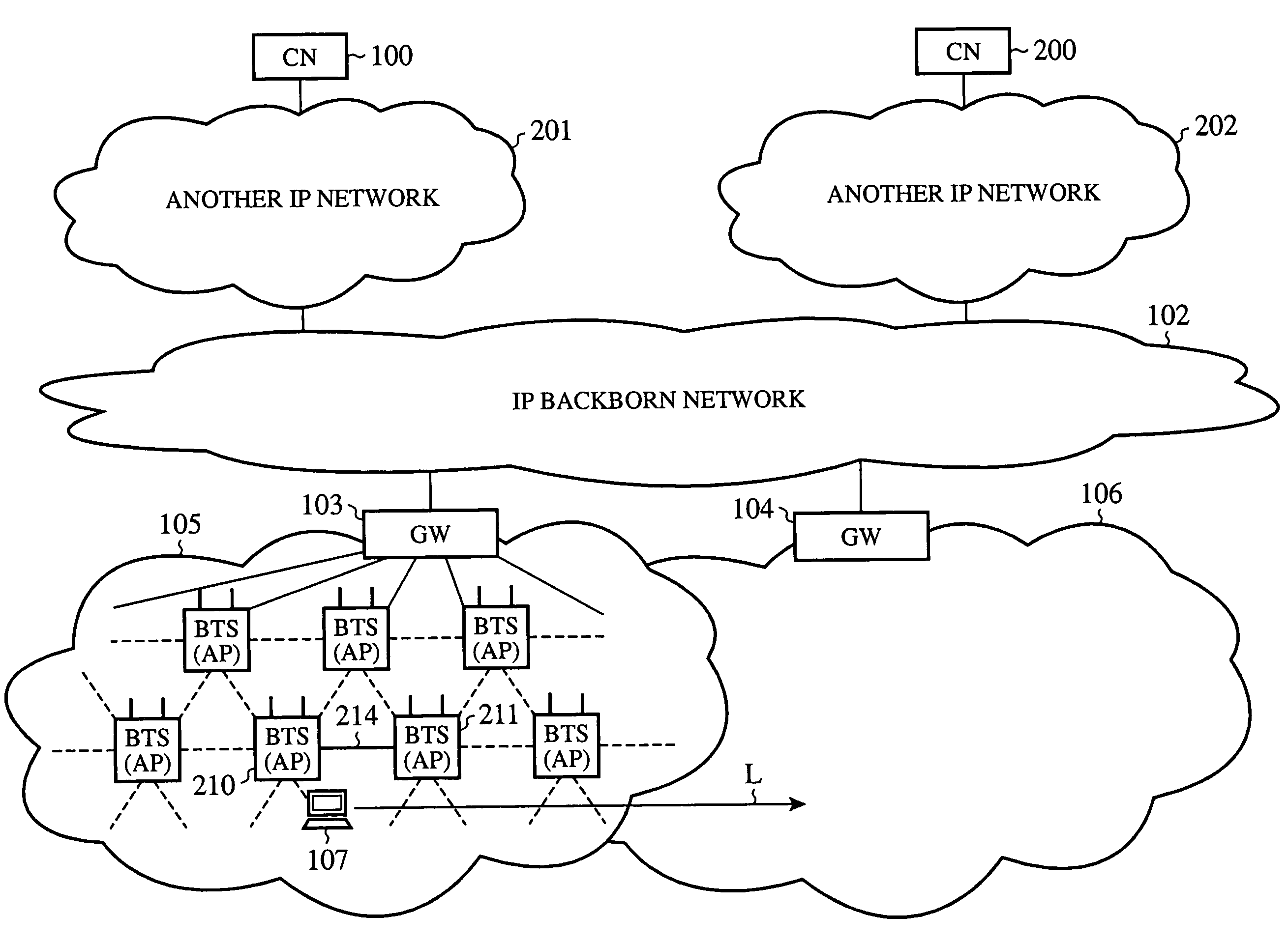
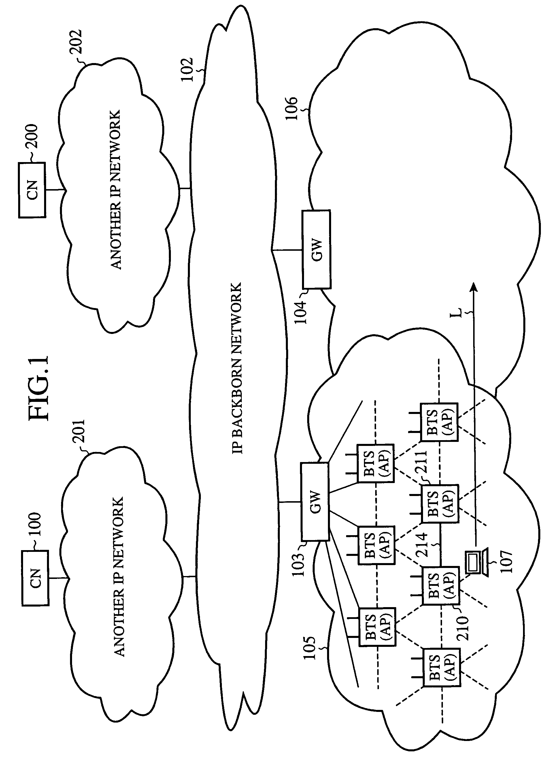
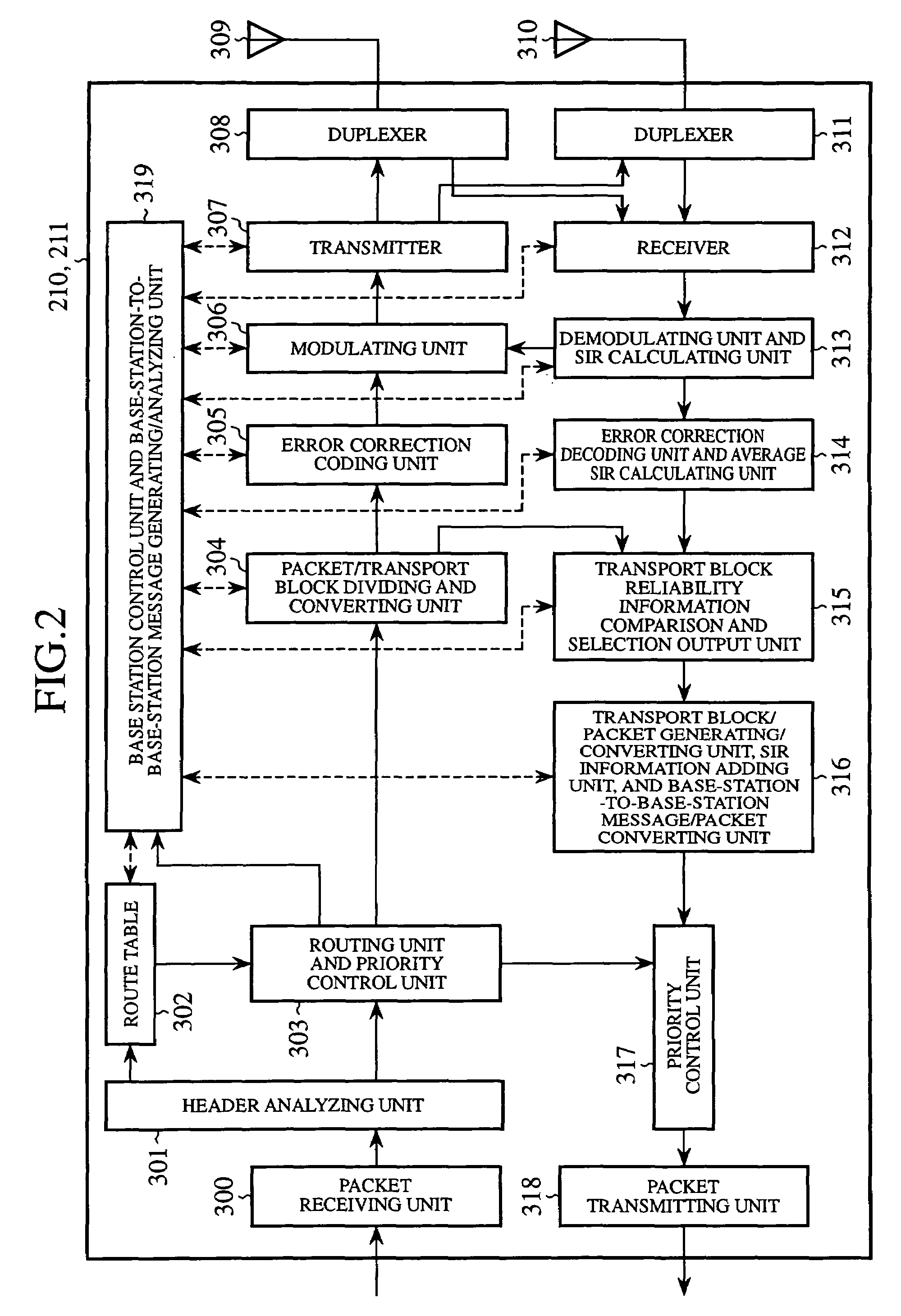
[0052]Embodiment 1 of the present invention will be now described hereafter with reference to FIGS. 1 to 5. FIG. 1 is a diagram showing the structure of a mobile communications system in accordance with embodiment 1 of the present invention, and FIG. 2 is a diagram showing the structure of a base transceiver station which constitutes the mobile communications system in accordance with this embodiment 1. FIGS. 3 to 5 are diagrams showing the operation of the mobile communications system in accordance with this embodiment 1.

[0053]As shown in FIG. 1, the mobile communications system in accordance with this embodiment 1 is provided with a global internet (i.e., an IP backbone network) 102 which is also connected to another IP network 201 (or 202) to which a communications-partner node 100 (or 200) with which a mobile node (Mobile Node) 107 is communicating belongs, a first boundary router (Gateway) 103 and a second boundary router (Gateway) 104 which form a boundary between the IP backb...

embodiment 2

[0109]Embodiment 2 of the present invention will be now described hereafter with reference to FIGS. 1, and 6 to 8. FIG. 1 is a diagram showing the structure of a mobile communications system in accordance with embodiment 2 of the present invention, and FIG. 6 is a diagram showing the structure of a base transceiver station which constitutes the mobile communications system in accordance with this embodiment 2. FIGS. 7 and 8 are diagrams showing the operation of the mobile communications system in accordance with this embodiment 2.

[0110]In above-mentioned embodiment 1, a mobile communications system which handles IP packets and supports a soft handover and a base transceiver station which constitutes the mobile communications system are explained. In accordance with this embodiment 2, a mobile communications system as shown in FIG. 1 uses a base transceiver station as shown in FIG. 3 instead of the base transceiver station of embodiment 1, so that the mobile communications system can...

embodiment 3

[0176]Embodiment 3 of the present invention will be now described hereafter with reference to FIGS. 1, and 9 to 11. FIG. 1 is a diagram showing the structure of a mobile communications system in accordance with embodiment 3 of the present invention, and FIG. 9 is a diagram showing the structure of a base transceiver station which constitutes the mobile communications system in accordance with this embodiment 3. FIGS. 10 and 11 are diagrams showing the operation of the mobile communications system in accordance with this embodiment 3.

[0177]In above-mentioned embodiment 1, a mobile communications system which handles IP packets and supports a soft handover and a base transceiver station which constitutes the mobile communications system are explained. In accordance with this embodiment 3, by simultaneously transmitting plural different transmission symbols from a plurality of transmission antennas using a base transceiver station as shown in FIG. 9, instead of the base transceiver sta...


PUM


Abstract

When carrying out a downlink handover, a source base transceiver station from which a mobile node is moving receives packets to be transmitted, via a wireless section, to the mobile node from an IP network, and copies and transfers them to a destination base transceiver station to which the mobile node is moving. On the other hand, when carrying out an uplink handover, the source base transceiver station compares the reliability of transport blocks which are received via a wireless section, from the mobile node and which are demodulated and decoded by the local station with that of transport blocks which are received via an IP network, from another base transceiver station and which are demodulated and decoded thereby, packetizes selected transport blocks with a better quality, and transmits them to a communications-partner node according to a route table, thereby implementing distribution of traffic via the IP network.

Description

FIELD OF THE INVENTION[0001]The present invention relates to an improvement in the efficiency of handoff processing and MIMO transmission by a base transceiver station for use in a mobile communications system which handles IP packets.BACKGROUND OF THE INVENTION[0002]A related art mobile communications system which handles IP packets is disclosed by, for example, “Trends in standardization of mobile communications protocols for the Internet” (Institute of Electronics, Information and Communication Engineers paper magazine 2001 / 10).[0003]According to Mobile IPv6, every time a mobile node moves, a binding response for updating of binding is exchanged between the mobile node and a home agent. Therefore, when the mobile node moves frequently, such control traffic causes congestions of the network.[0004]Furthermore, when it takes much time for the mobile communications system to carry out binding with a home agent or a communications-partner node, packets are relayed to a location where ...

Claims


Application Information

Patent Timeline
Patent Type & Authority Patents(United States)
IPC IPC(8): H04Q7/20G06F11/00H04L45/243H04L45/74H04L45/80H04L47/2416H04W16/28H04W28/04H04W36/02H04W36/18H04W36/30H04W36/36H04W40/24H04W40/34H04W40/36H04W80/04
CPCH04L45/00H04W36/02H04W36/0016H04L69/22H04W36/18H04W40/36H04W80/04H04W40/248
Inventor TOMOE, NAOHITOSUYAMA, SYOUHEI
Owner MITSUBISHI ELECTRIC CORP
Why Eureka
Try Eureka