
A traffic signal lamp control method and traffic signal lamp system

A technology of traffic signal lights and control methods, which is applied in the field of traffic signal light control, can solve problems such as intersection paralysis and intersection congestion, and achieve the effect of ensuring normal operation

Inactive Publication Date: 2008-02-13
深圳市哈工交通电子有限公司
View PDF0 Cites 62 Cited by
  • Summary
  • Abstract
  • Description
  • Claims
  • Application Information

AI Technical Summary

Problems solved by technology

As a result, the entire intersection will be congested and the entire intersection will be paralyzed. The current control strategy of the signal machine cannot solve this problem, and it can only be solved by manual command.

Method used


Image

  • A traffic signal lamp control method and traffic signal lamp system
  • A traffic signal lamp control method and traffic signal lamp system

Examples


Embodiment Construction

[0013] The present invention will be further elaborated below according to the drawings and specific embodiments.

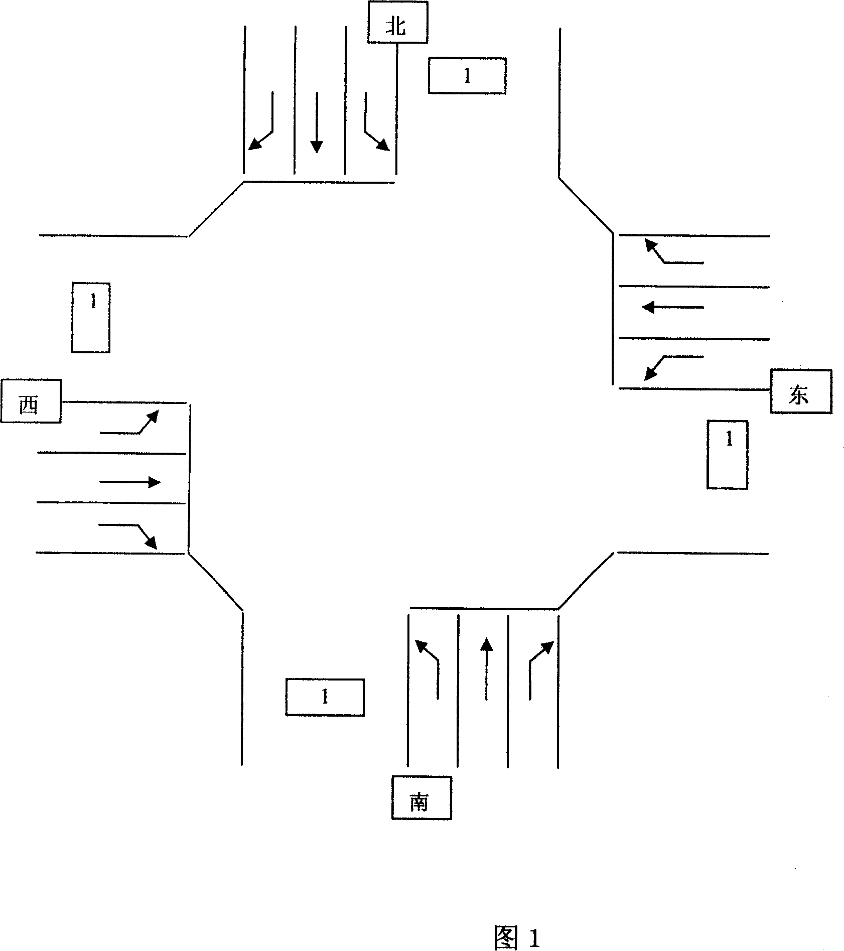
[0014] A traffic signal light system of the present invention includes a traffic signal light, a traffic flow detector and a signal light controller, and only the position of the traffic flow monitor is shown in the accompanying drawing 1, as shown in the box marked 1 in the figure. Traffic lights and signal light controllers can be set according to specific conditions. Wherein, the traffic signal lamp and the traffic flow detector are connected with the signal lamp controller, and receive the control of the signal lamp controller. The traffic flow detector can be one or a combination of coil detectors, video detectors, ultrasonic detectors, microwave detectors, geomagnetic detectors, active and passive infrared detectors, piezoelectric detectors and audio detectors, as long as it can be real-time The traffic flow information on the road is detected and sent to ...


PUM


Abstract

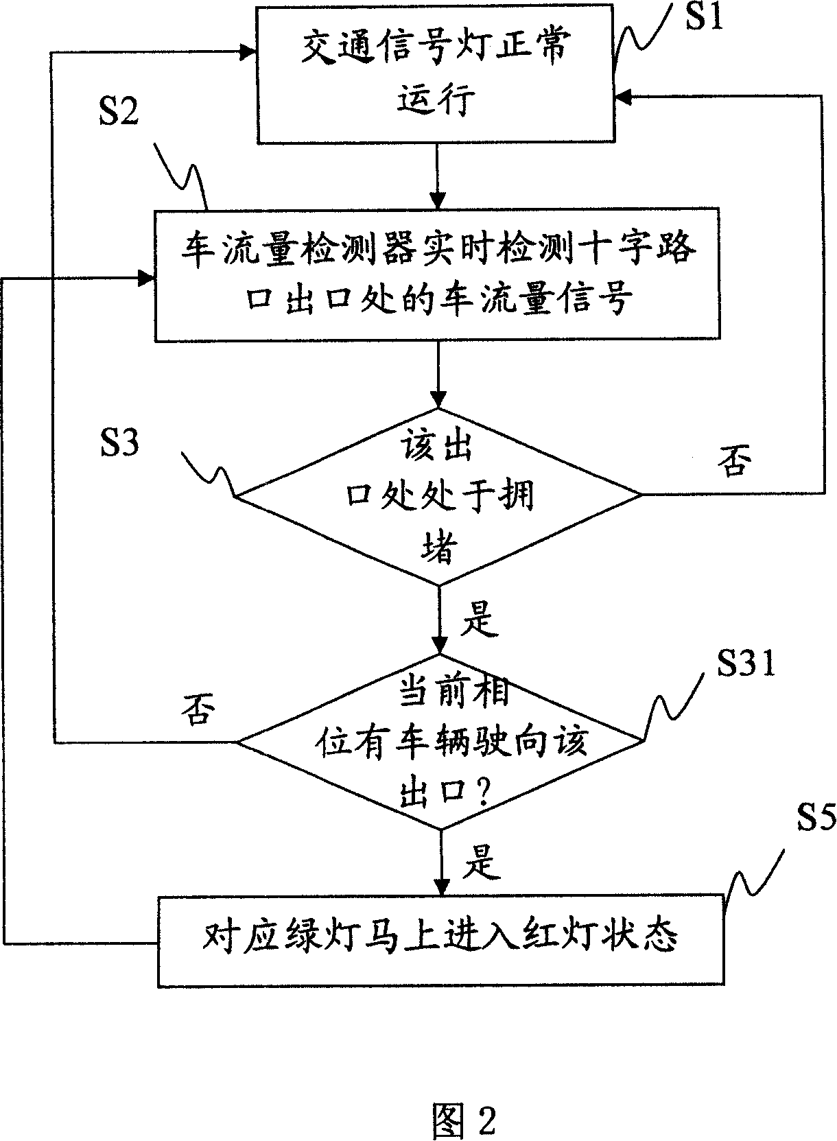
The invention discloses a traffic light control method. A traffic flow detector is used for real-time detecting traffic flow signal at the exit of a crossing, and when the exit is identified in jam status, the signal lights for coming to the crossing are all turned red, until the jam status is released. The invention also discloses a traffic light system. The invention is used for real-time detecting vehicle status at the exit of a crossing, and when the exit is in jam status, the invention prevents vehicle from further moving to the exit. The invention prevents vehicles from jamming the whole crossing, and ensures normal running of vehicles in other directions.

Description

technical field [0001] The invention relates to a traffic signal light control method and system, in particular to a traffic signal light control method and a traffic signal light system for adjusting traffic signal light signals according to the output signal of a traffic flow detector. Background technique [0002] At present, the more advanced traffic signal controllers have the function of induction control. The principle is to adjust the green light time of the current phase in real time according to the traffic flow signal at the corresponding entrance detected by the vehicle detector (ground induction coil, video detector) to achieve The purpose of matching signal timing with traffic flow. For example, if the vehicle detector detects that the traffic flow at the entrance of a crossroad is larger than that at other entrances, the green light lighting time corresponding to the entrance will be extended. Because this technology is to adjust the green light time, it can ...

Claims


Application Information

Patent Timeline
Patent Type & Authority Applications(China)
IPC IPC(8): G08G1/08G08G1/01
Inventor 曹泉
Owner 深圳市哈工交通电子有限公司
Learn More