Prosthesis

a technology of prosthesis and inner shell, applied in the field of prosthesis, can solve the problems of inability to achieve construction, inability to achieve effective practice, and inability to tighten the strings of the inner shell

Inactive Publication Date: 2004-08-12
LUISA CERANO
View PDF9 Cites 65 Cited by
  • Summary
  • Abstract
  • Description
  • Claims
  • Application Information

AI Technical Summary

Problems solved by technology

This is unsatisfactory because of the expenditure of time and particularly money connected therewith.
Although it was good thinking, this construction did not prove itself and was not successful in practice.
However, after closing the tightening strings for the outer shell, the tightening strings for the inner shell are no longer accessible, that is, their fasteners are not accessible anymore.
Attaching and detaching of such a prosthesis shaft is, therefore, extremely cumbersome and time-consuming.
In addition, prosthesis shafts made of lamellae cannot develop a vacuum for firm attachment to the limp stump.
This construction also did not succeed in practice.
The limb stump then no longer sits correctly with a conical bearing surface that is provided in each prosthesis shaft and can, for example, no longer optimally transfer the body weight to the prosthesis.
This is unsatisfactory.
This increases the expenditure of time and money.
The connection between the lamellae with only one rivet, however, has the disadvantage that it weakens the stability of the prosthesis shaft.

Method used


Image

  • Prosthesis
  • Prosthesis
  • Prosthesis

Examples


Embodiment Construction

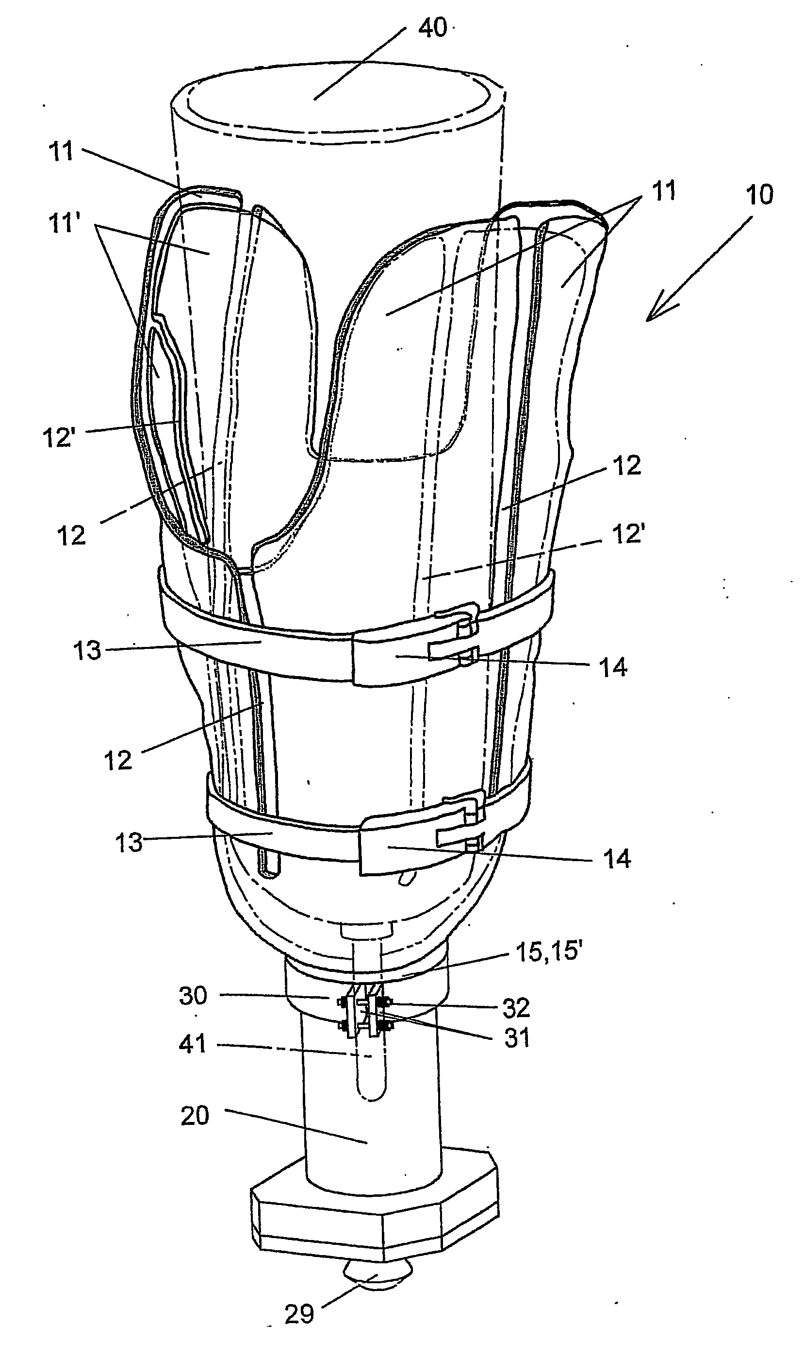
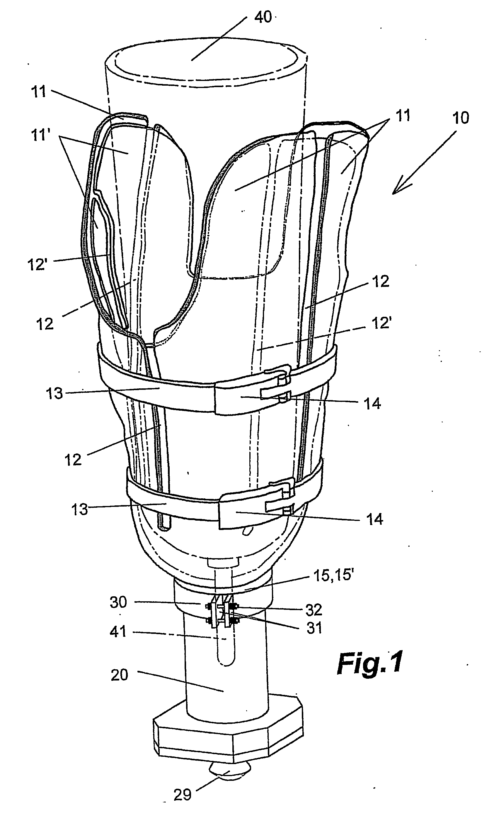
[0012] It is therefore an object of the present invention to disclose a prosthesis as previously described, which can be fabricated simply and thanks to prefabrication can be produced in greater series, cost-efficiently, having a great solidity and fits within predetermined limits to limb stumps, whereby a diameter and length can be changed.

[0013] The problem is solved with a prosthesis with the features of claim 1, essentially comprising

[0014] a silicone liner with a coupling pin,

[0015] a prosthesis shaft

[0016] fitted to a limb stump,

[0017] provided with longitudinal slits in some areas,

[0018] and adjustable in diameter using tightening elements,

[0019] and a fastener for connecting an artificial limb with the prosthesis shaft,

[0020] the longitudinal slits are bridged over,

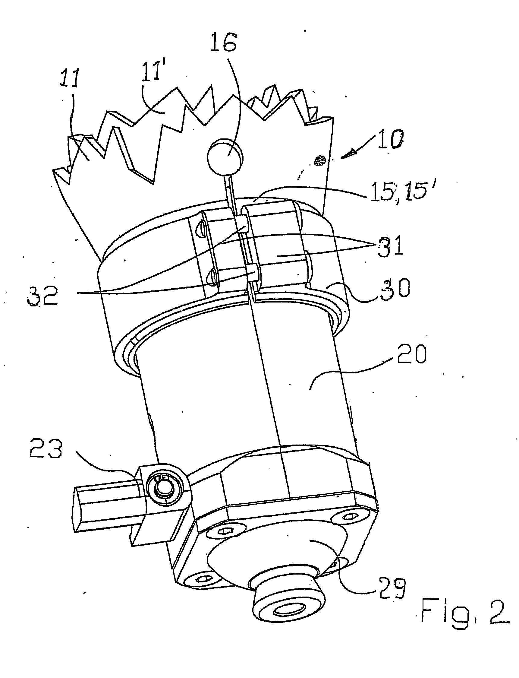
[0021] the prosthesis shaft has a concentric band,

[0022] inside the band, a cylindrical adaptor is height-adjustably mounted,

[0023] the adaptor

[0024] has

[0025] at its upper end a bearing surface for the limb stump...


PUM


Abstract

The invention relates to prostheses for amputated patients. The shaft of the prosthesis (10) consists of an outer shell (11) and a concentric inner shell (11'). Both shells are provided with longitudinal slits (12, 12') which are staggered in relation to each other and extend essentially in the axial direction. The diameter of the shaft (10) of the prosthesis can be adjusted by means of tightening elements (13, 14). An adapter (20) is fixed in the shaft of the prosthesis (10) in such a way that the height of said adapter can be adjusted. A conical bearing surface for the stump of the limb is provided on the upper side of the adapter (20), a holding element (29) for fixing an artificial limb is provided on the lower side of the same, and a coupling is provided inside the adapter for detachably fixing the coupling pin (41) of a commercially available silicone liner (40).

Description

[0001] The invention relates to prostheses according to the preamble of claim 1, essentially comprising a silicone liner with a coupling pin, a prosthesis shaft adapted to a limb stump, provided with longitudinal slits in some areas, the diameter being adjustable by means of tightening elements, and a holding device to connect artificial limbs with the shaft of the prosthesis.CONVENTIONAL ART[0002] It is the purpose of prostheses to replace as best as possible limbs that were lost through an accident or illness. To temporarily attach prostheses, for example artificial hands or feet, to a limb stump, special prosthesis shafts are used, which must be anatomically fitted to the limb stump. The attachment is commonly achieved by a vacuum between the prosthesis shaft and the limb stump or between the limb stump and a silicone liner.[0003] Prosthesis shafts are made of metal, wood or cast resin. There are shafts of longitudinal or cross-oval shape, full-contact shafts, with a valve, or a ...

Claims


Application Information

Patent Timeline
Patent Type & Authority Applications(United States)
IPC IPC(8): A61F2/00A61F2/50A61F2/54A61F2/60A61F2/76A61F2/78A61F2/80
CPCA61F2/54A61F2230/0086A61F2/76A61F2/78A61F2/7812A61F2/80A61F2002/30276A61F2002/30334A61F2002/30354A61F2002/30401A61F2002/30464A61F2002/30492A61F2002/30505A61F2002/30509A61F2002/30517A61F2002/30522A61F2002/5003A61F2002/502A61F2002/5026A61F2002/5027A61F2002/503A61F2002/5055A61F2002/5075A61F2002/5081A61F2002/5083A61F2002/7856A61F2002/7862A61F2002/7881A61F2002/7893A61F2220/0025A61F2220/0033A61F2220/0075A61F2/60A61F2002/30462A61F2002/30507
Inventor CARSTENS, JOHANNES
Owner LUISA CERANO
Why Eureka
Try Eureka