X-ray target assembly for high speed anode operation

a high-speed anode and target assembly technology, applied in the direction of x-ray tube target geometry, x-ray tube bonding/fixing, electric discharge tubes, etc., can solve the problems of high hub stress, increase in power requirements and associated wear of such assemblies, and increase in the complexity and capabilities of modern medical imaging assemblies

Active Publication Date: 2007-02-22
GENERAL ELECTRIC CO
View PDF5 Cites 22 Cited by
  • Summary
  • Abstract
  • Description
  • Claims
  • Application Information

AI Technical Summary

Problems solved by technology

Modern medical imaging assemblies have increased in complexity and capabilities.
These increases often result in an increase in power requirements and associated wear on such assemblies.
These increased rotational speeds may result in high hub stresses that exceed present design criteria.
In addition to the additional stresses associated with the increase in power requirements, the target assembly itself will suffer an increase in wear and thermal damage.
These increases stressors are well known to result in damage to the impact regions of the target element.
The increase in thermal energy in combination with the increased stresses due to increased rotational speeds may result in undesirable wear and damage to the hub element.
In any design for an x-ray target assembly it is likely that the target element or portions thereof will suffer damaged during prolonged usage.
Yet when wear or damage becomes too great, existing designs require complete replacement.
Disassembly and repair is not contemplated by existing designs and may be impractical based on design configurations and associated costs.

Method used


Image

  • X-ray target assembly for high speed anode operation
  • X-ray target assembly for high speed anode operation
  • X-ray target assembly for high speed anode operation

Examples


Embodiment Construction

)

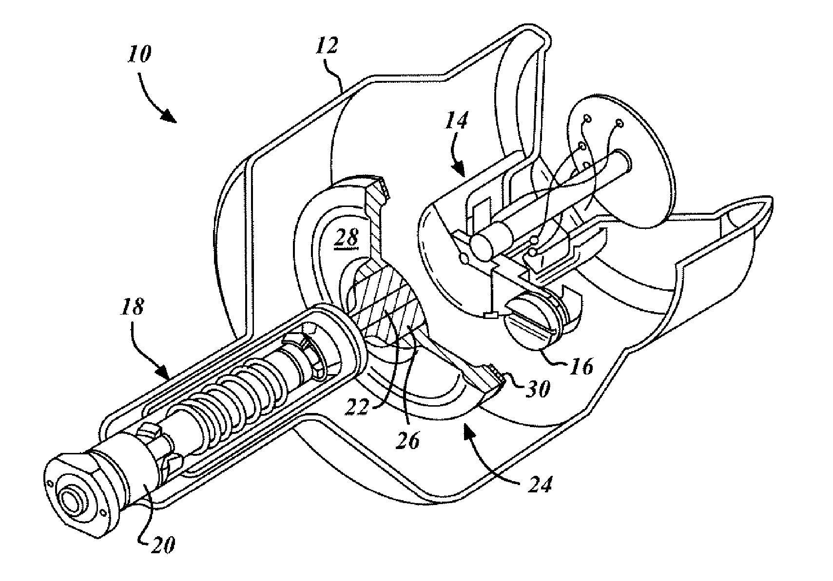
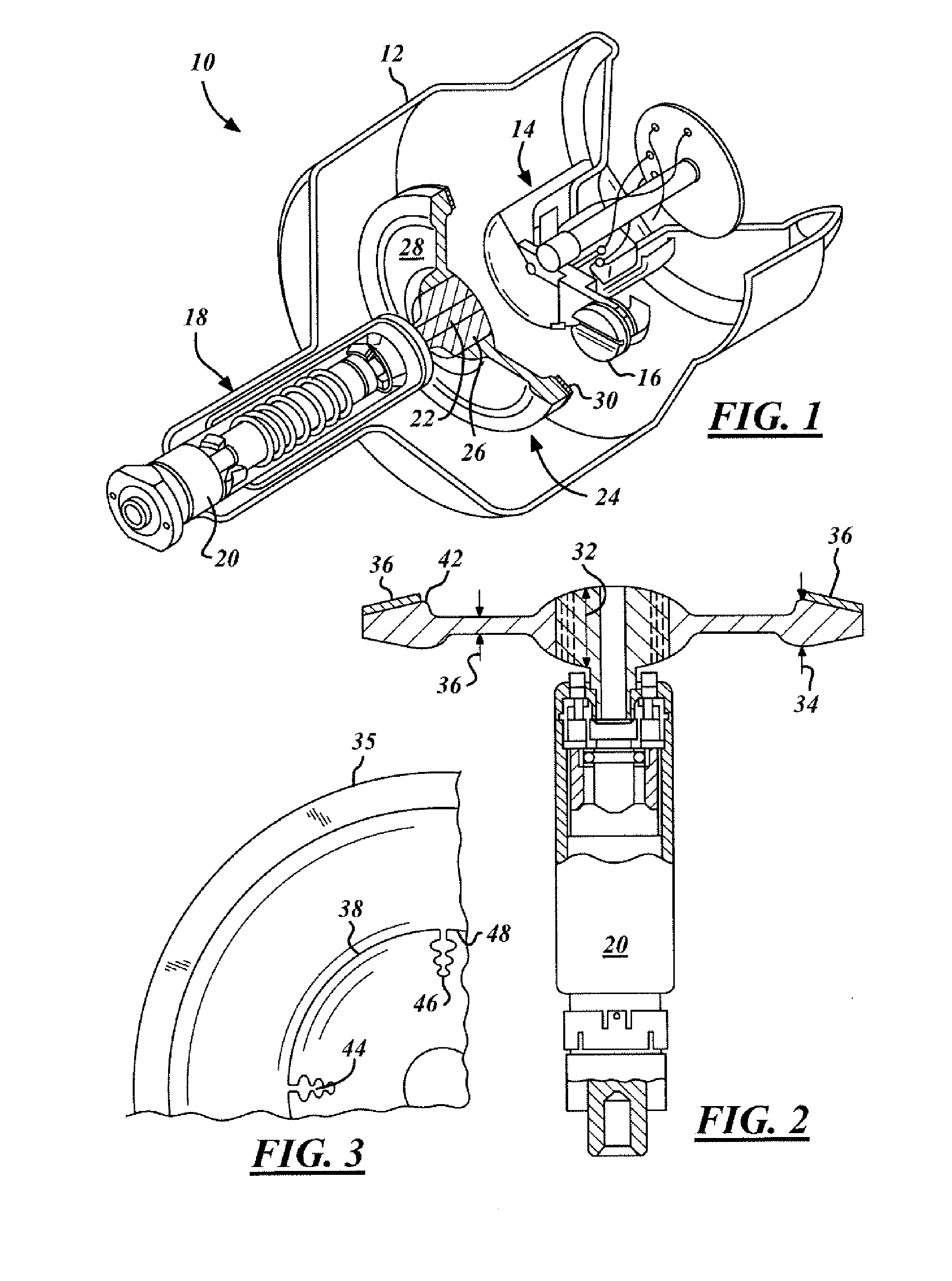
[0014] Referring now to FIG. 1, which is an illustration of an x-ray tube assembly 10 in accordance with the present invention. The assembly 10 includes a tube casing 12. A variety of tube casings 12 are contemplated by the present invention. Within the tube casing 12 includes a cathode assembly 14 wherein electrons are gathered and discharged through an cathode discharge cup 16 towards an anode assembly 18. The anode assembly 18 is comprised of an anode drive assembly 20 rotating an anode drive shaft 22 which in turn rotates an x-ray tube target assembly 24. As is well known in x-ray tube art, the electrons generated by the cathode assembly 14 impact the x-ray tube target assembly 24 and result in the production of gamma or x-rays.

[0015] The impact of electrons on the x-ray tube target assembly 24 generates considerable heat and considerable wear. The present invention contemplates such stressors by forming the x-ray tube target assembly 24 as a center hub element 26 and an outer...


PUM


Abstract

An x-ray target assembly is provided comprising a center hub element affixed to a drive shaft and an outer disc including a plurality of tab extensions removably engaging the periphery of the center hub element. A target element is mounted on an upper outer disc surface.

Description

TECHNICAL FIELD [0001] The present invention relates generally to an x-ray target assembly and more particularly to an x-ray target assembly with separate hub and disc elements. BACKGROUND OF THE INVENTION [0002] Modern medical imaging assemblies have increased in complexity and capabilities. These increases often result in an increase in power requirements and associated wear on such assemblies. Such is the case with x-ray tube assemblies. Increases in power requirements of the imaging assembly can result in increases in the required rotational speed of the x-ray target assembly in order to prevent overheating and damage thereto. These increased rotational speeds may result in high hub stresses that exceed present design criteria. The hub is the center portion of a target assembly in communication with the drive shaft. [0003] In addition to the additional stresses associated with the increase in power requirements, the target assembly itself will suffer an increase in wear and ther...

Claims


Application Information

Patent Timeline
Patent Type & Authority Applications(United States)
IPC IPC(8): H01J35/10
CPCH01J35/101H01J2235/083H01J2235/086H01J2235/1013H01J2235/1295
Inventor HOCKERSMITH, RON K.HEBERT, MICHAEL SCOTT
Owner GENERAL ELECTRIC CO
Why Eureka
Try Eureka