
Ventilating device, especially for a motor vehicle alternator

a technology of electric motor and ventilation device, which is applied in the direction of machines/engines, mechanical apparatus, liquid fuel engines, etc., can solve the problems of difficult to obtain a large number of blades of the desired form, mechanical friction also occurs in operation, and achieve the effect of the greatest possible stiffness

Active Publication Date: 2007-02-22
VALEO EQUIP ELECTRIC MOTEUR
View PDF3 Cites 7 Cited by
  • Summary
  • Abstract
  • Description
  • Claims
  • Application Information

AI Technical Summary

Benefits of technology

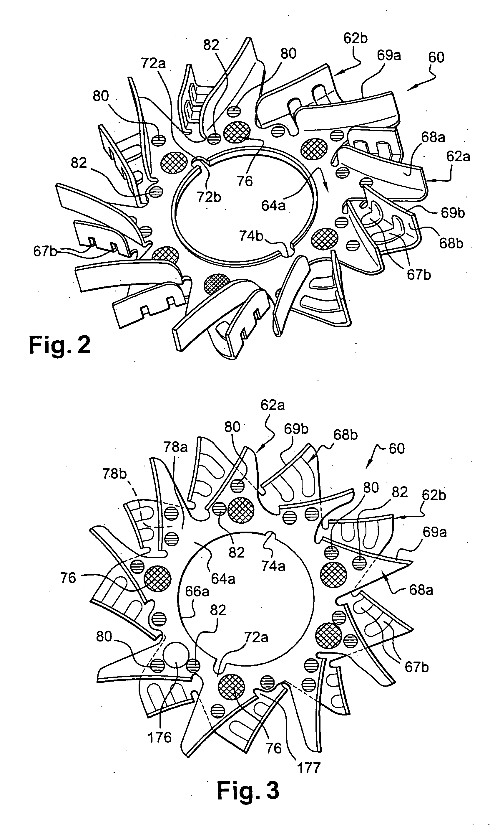
[0025] Thus, the branches are configured in such a way that they have overlapping zones which, in combination with the fastening points, enable the ventilating device to be stiffened while at the same time leaving enough space in the region of the annular central part of the radial plate portions for fastening on the rotor.
[0039] Thanks to this arrangement, the fastening points enable the presence of stiffening ribs for the blades and branches of one of the fans, or even for both fans, to be eliminated.

Problems solved by technology

Mechanical friction also occurs in operation.
This friction contributes to the heating of the machine.
That type of ventilating device does give satisfaction, but in some cases it can be difficult to obtain a large number of blades of the desired form.

Method used


Image

  • Ventilating device, especially for a motor vehicle alternator
  • Ventilating device, especially for a motor vehicle alternator
  • Ventilating device, especially for a motor vehicle alternator

Examples


Embodiment Construction

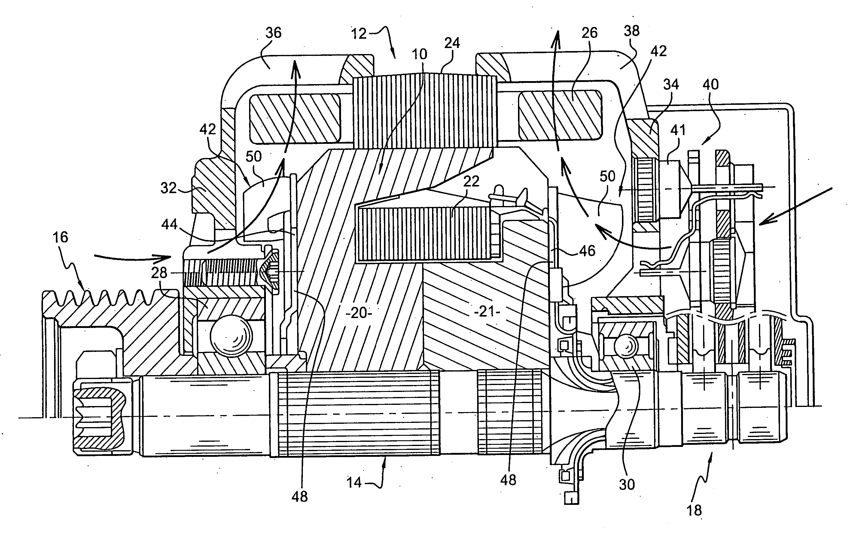
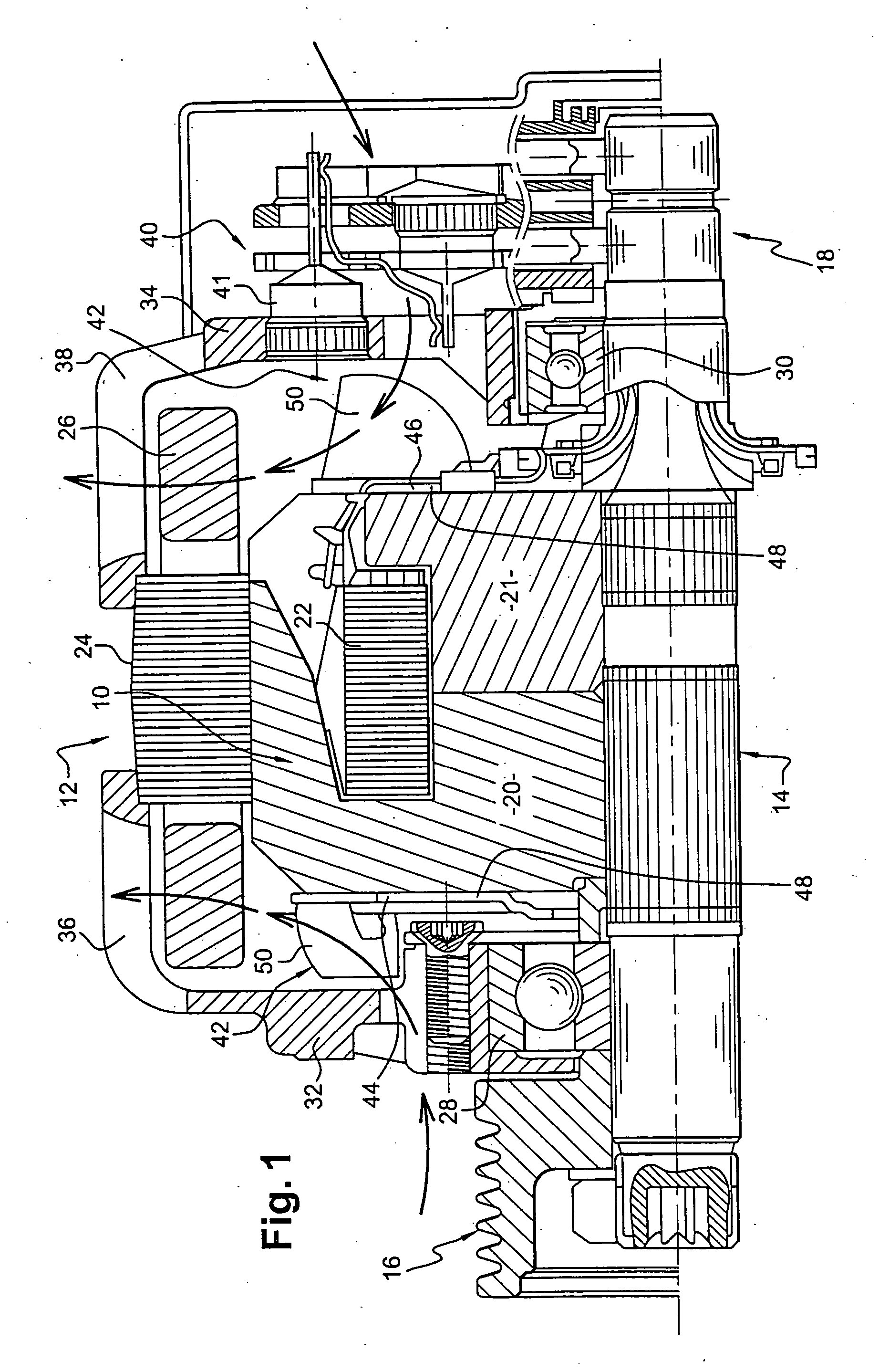
[0064] The sole purpose of FIG. 1 is to recall briefly the general structure of a polyphase alternator with internal ventilation, for a heat engine of a motor vehicle, with a view to putting the invention in its preferred context of use.

[0065] For the understanding of the invention, it is sufficient to indicate that the alternator shown comprises essentially a rotor 10 surrounded by a stator 12 and mounted rotatably on a rotor shaft 14, the front end of which carries a drive pulley 16 for rotation with it, while the rear end carries slip rings (not given reference numerals) which are part of a collector 18. The pulley 16 is arranged to be coupled to the heat engine of the vehicle through a belt transmission.

[0066] In this example, the rotor 10 is of the claw type, and comprises two pole wheels designated by the references 20 and 21, which have axially oriented teeth offset circumferentially as between one wheel and the other. The reference 22 designates the excitation winding of t...


PUM


Abstract

The ventilating device, adapted to be fixed on a rotor of a rotary electrical machine, comprises a first fan (62a) having a radial plate portion (64a), at least one second fan (62b) having a radial plate portion (64b), and means for fastening the two fans (62a, 62b), each fan (62a, 62b) having, at the outer periphery of its radial plate portion, first branches (78a) and second branches (78b) which extend radially outwards, at least some of the branches having a blade (68a, 68b), while at least one first branch (78a) and at least one second branch (78b) includes a first (78a) and a second (78b) mutual overlapping portion to define an overlap zone (Z), the said fastening means (80, 82) being at least partly arranged at the level of the overlap zone.

Description

FIELD OF THE INVENTION [0001] The present invention relates to a ventilating device for a rotary electrical machine, especially for a motor vehicle. [0002] Such a machine may be an alternator or an alternator-starter for a motor vehicle, or some other type of rotary electrical machine, and is described for example in the documents FR-A-2 602 925 and JP-A-6 121 497, to the contents of which reference may be made for more details. [0003] This machine includes a hollow support for fastening the machine on a fixed part, a stator, and a rotor which carries at least one ventilating device. [0004] The stator surrounds the rotor, which is fixed on a rotor shaft. [0005] The support carries the stator at its outer periphery, and has bearings arranged centrally, such as rolling bearings with one or two rows of balls, for mounting the rotor shaft in rotation in such a way that the rotor and stator are mounted within the support, the latter including two parts which are called the front bearing ...

Claims


Application Information

Patent Timeline
Patent Type & Authority Applications(United States)
IPC IPC(8): H02K9/06F03B7/00F04D29/28
CPCF04D29/281
Inventor VASILESCU, CLAUDIUTELLIER, RICHARDKIM, NAM-GOOK
Owner VALEO EQUIP ELECTRIC MOTEUR
Learn More