Linear roller bearing with bonded rolling surface parts

a technology of linear roller bearings and rolling surface parts, which is applied in the direction of sliding contact bearings, mechanical equipment, instruments, etc., can solve the problems of difficult to create adhesive supply channels, difficult to use, and large space requirements for adhesive/force-fit connections, etc., and achieve the effect of increasing stiffness

Inactive Publication Date: 2012-08-28
ROBERT BOSCH GMBH
View PDF20 Cites 5 Cited by
  • Summary
  • Abstract
  • Description
  • Claims
  • Application Information

AI Technical Summary

Benefits of technology

[0006]The object of the present invention is to provide an adhesive connection that has increased stiffness. The installation space required for the guide carriage should not be increased as a result.
[0009]The adhesive is located in the openings in the sheet-metal panel, and its function is essentially to hold the rolling surface part in position, that is, to essentially prevent the rolling surface part from becoming displaced traversely relative to the plane of the sheet-metal panel. The overall cross-sectional area of the openings and the supporting surface of the thin sheet-metal panel are matched to one another such that the linear roller bearing has the desired level of stiffness, while the adhesive layer reliably performs its holding function. The thickness of the thin sheet-metal panel corresponds to the thickness of the adhesive layer and is therefore very thin. Accordingly, the present adhesion requires very little space. The thin sheet-metal panel is preferably a flat sheet-metal panel that is installed between flat surfaces of the assigned rolling surface part and the main body. The sheet-metal panel preferably has a shape that is adapted to the rolling surface part, and, in particular, the width of the sheet-metal part is essentially equal to the width of the rolling surface part. The greatest possible stiffness of the linear roller bearing is obtained as a result.
[0011]A large number of openings that are preferably formed in the thin sheet-metal panel using a photochemical etching method is provided. The purpose of the large number of openings is to ensure that the load transfer between the rolling surface part and the main body takes place such that it is distributed as evenly as possible. Since the sheet-metal panel according to the present invention is very thin, the large number of openings may be created in the thin sheet-metal panel in one working step using a photochemical etching method, thereby ensuring that the sheet-metal panel is particularly cost-effective to manufacture. Particularly preferably, the sheet-metal panel is manufactured using a continual etching method, thereby resulting in a substantially endless sheet-metal panel that may simply be cut to the desired length. The manufacturing costs may be reduced further as a result.
[0013]The sheet-metal panel may have a thickness between 20 μm and 200 μm. The adhesive layer in the openings therefore has a thickness that has particularly favorable load-transferring properties. At the same time, the openings in a sheet-metal panel of this type may be easily created using the aforementioned etching process.
[0016]Several parallel rows of rectangular openings that are offset relative to one another may be provided. This results in a particularly flexible sheet-metal panel that is capable of easily adapting to possible uneven areas in the assigned rolling surface part and the main body without plastic deformations occurring.
[0019]The purpose of this is to prevent the stiffness of the linear roller bearing from being reduced by the presence of the sensor. Another purpose is to avoid overloading the sensor. This goal may be attained in a particularly cost-favorable manner by locating the sensor, preferably a piezoceramic sensor, in an opening in the thin sheet-metal panel. The corresponding opening for the sensor preferably has a shape that is adapted to the requirements of the sensor and that deviates from the shape of the openings for the adhesive.

Problems solved by technology

The disadvantage of the state of the art is that the adhesive / force-fit connection requires a great deal of space, since a special projection that engages in a groove in the main body must be provided on the rolling surface part.
In addition, various adhesive supply channels must be provided in the guide carriage in order to create the adhesive layer, and these adhesive supply channels are difficult to create.
Furthermore, it is not possible using the proposed solution to create an adhesive layer having just any thickness, and therefore the stiffness of the linear roller bearing is reduced anyway.
The disadvantage of the design according to EP 1 808 608 A1 is that the adhesive layers are very thick, with the result that the stiffness of the linear roller bearing is greatly reduced.

Method used


Image

  • Linear roller bearing with bonded rolling surface parts
  • Linear roller bearing with bonded rolling surface parts
  • Linear roller bearing with bonded rolling surface parts

Examples


Embodiment Construction

[0025]A linear roller bearing according to the present invention may be created by starting with the linear roller bearing known from DE 10 2007 056 862 and replacing the carriage rolling surfaces designed as single pieces with the main body with the rolling surface parts which are described below and include the carriage rolling surfaces. DE 10 2007 056 862 is therefore referenced in entirety and is incorporated in the contents of the present application.

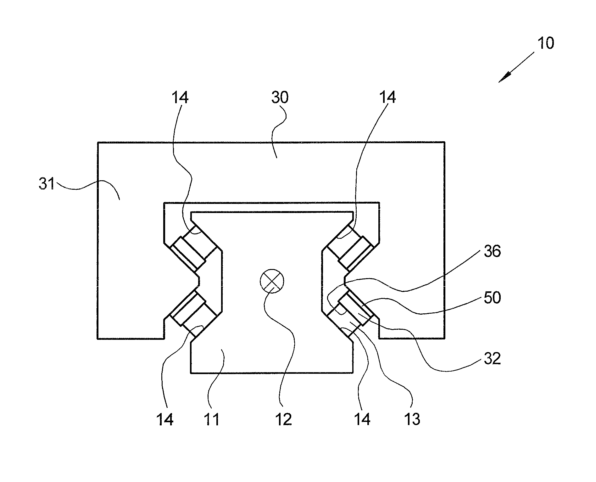
[0026]FIG. 1 shows a basic schematic cross section of a linear roller bearing 10 according to the present invention. Linear roller bearing 10 includes a guide rail which is composed of hardened roller bearing steel and extends in a longitudinal direction 12; longitudinal direction 12 is oriented perpendicularly to the plane of the drawing. Guide rail 11 has a substantially constant cross-sectional shape along its entire longitudinal extension; a total of four flat rail rolling surfaces 14 are provided for the substantially circular...


PUM

PropertyMeasurementUnit
thicknessaaaaaaaaaa
thicknessaaaaaaaaaa
thicknessaaaaaaaaaa

Abstract

A guide carriage for a linear roller bearing is supportable in a longitudinally displaceable manner via a large number of rolling elements on a guide rail which extends in a longitudinal direction, and has at least one rolling surface part including at least one carriage rolling surface for the rolling elements and is attached to a main body of the guide carriage via at least one adhesive layer, and a thin sheet-metal panel which has at least one opening is located between the rolling surface part and the main body, with the adhesive layer located inside the opening.

Description

CROSS-REFERENCE TO A RELATED APPLICATION[0001]The invention described and claimed hereinbelow is also described in German Patent Application DE 10 2008 051 682.1 filed on Oct. 15, 2008. This German patent application, whose subject matter is incorporated here by reference, provides the basis for a claim of priority of invention under 35 U.S.C. 119(a)-(d).BACKGROUND OF THE INVENTION[0002]The present invention relates to a guide carriage for a linear roller bearing Linear roller bearings in the sense of the present invention are, e.g., bearing rail guides, roller rail guides, bearing bushes, and ball splines.[0003]The disadvantage of the state of the art is that the adhesive / force-fit connection requires a great deal of space, since a special projection that engages in a groove in the main body must be provided on the rolling surface part. In addition, various adhesive supply channels must be provided in the guide carriage in order to create the adhesive layer, and these adhesive supp...

Claims


Application Information

Patent Timeline
Patent Type & Authority Patents(United States)
IPC IPC(8): F16C19/00F16C17/00G01L3/14
CPCF16C29/00F16C29/0604F16C29/065F16C33/64F16C41/00F16C2226/40
Inventor ALBERT, ERNST
Owner ROBERT BOSCH GMBH
Why Eureka
Try Eureka