
Method and device for weightlifting and weight training

Active Publication Date: 2007-02-22
PANAGOS GEORGE C
View PDF26 Cites 10 Cited by
  • Summary
  • Abstract
  • Description
  • Claims
  • Application Information

AI Technical Summary

Benefits of technology

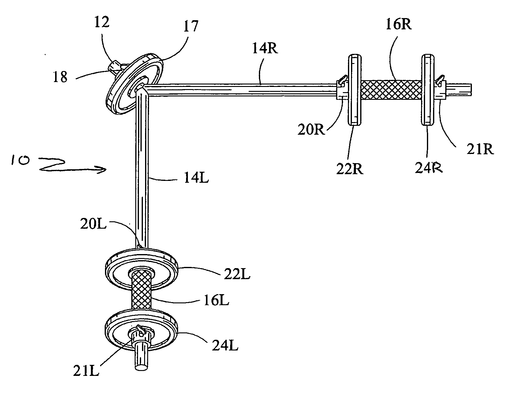
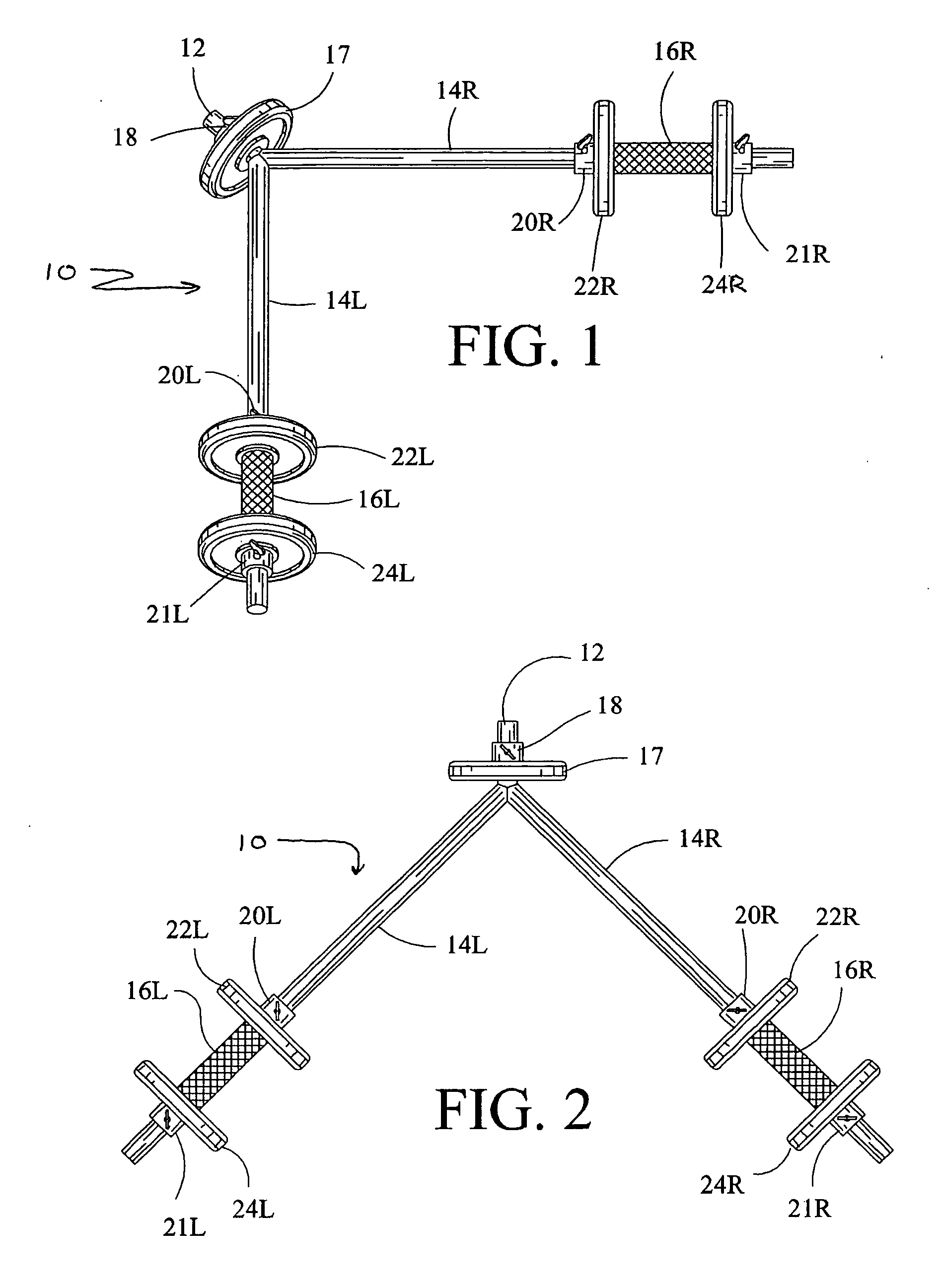
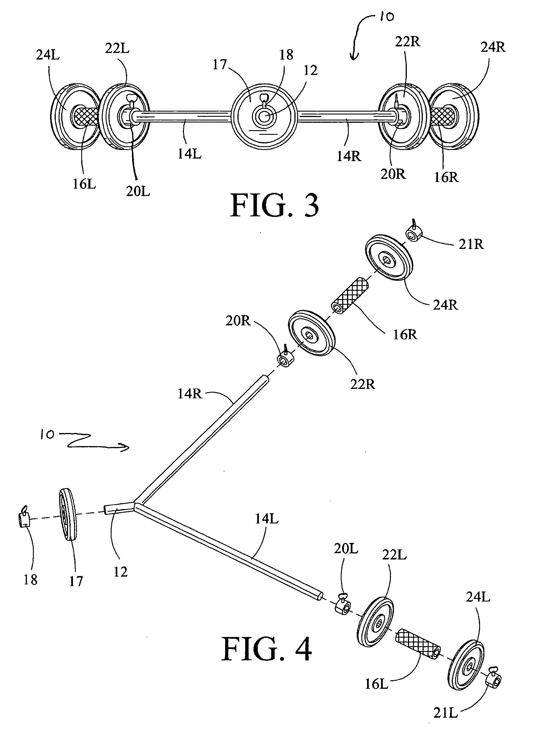
[0006] The foregoing and other objects are achieved in accordance with the present invention, a novel method and device for weightlifting and weight training incorporating a weighted V-shaped exercise bar. The device of the present invention is a solid, weighted exercise bar with two wings and an apex—its shape is similar to that of a “V”. The wings contain handle grips and are capable of having weight plates, discs and collars attached. The apex contains a projecting post that extends in an outward direction and holds an adjustable weight, thereby allowing the user to bal

Problems solved by technology

However, because of conventional dumbbells and barbells' universal nature, they are limited in their effectiveness to isolate certain muscles of the body.
However, these V-shaped apparatuses are bulky and unwieldy, are not balanced properly, and limit the handle gr

Method used


Image

  • Method and device for weightlifting and weight training
  • Method and device for weightlifting and weight training
  • Method and device for weightlifting and weight training

Examples


embodiment 30

[0027] An alternative embodiment 30 of the present invention is depicted in FIG. 5. Alternative embodiment 30 comprises a spherically weighted apex post 32, a pair of wing posts 34L and 34R, a pair of handle grips 36L and 36R affixed to wing posts 34L and 34R, respectively, and wing post weights 38L and 38R permanently attached to the bottom end of wing posts 34L and 34R, respectively.

[0028] Wing posts 34L and 34R are fabricated from the same materials used to make standard or conventional barbells and dumbbells. Apex post 32 and wing posts 34L and 34R are permanently joined at the point where wing posts 34L and 34R meet to form a “V” using methods to connect the apex post 32 with the wing posts 34L and 34R that are known and used in the art. Wing posts 34L and 34R form an angle more than 10° and less than 180°. The preferred angle is in the range of more than 45° up to about 90°. The apex post 32 and wing post weights 38L and 38R can be ball-shaped, cubed-shaped, hexagon-shaped, or...

embodiment 10

[0035] Weights can be added or removed from preferred embodiment 10 to suit the weightlifters particular strengths and exercises. Similarly, heavier or lighter alternative embodiments 30, 30′ or 30″ may be used to perform the methods described above.

[0036] The above described methods can be modified to suit the weightlifter's individual desires. Other exercises that can be performed using conventional dumbbells and barbells are possible and contemplated by the inventor using the exercise device described herein.

[0037] Thus, as can be readily appreciated, the method and exercise device of the present invention can substantially advance the efficient weight training of the upper and lower body that conventional dumbbells and barbells fail to achieve. In particular, because the apex of the exercise device of the present invention contains a projecting post that holds weight, the exercise device allows the weightlifter to balance and counter balance the weights on the wings of the devi...


PUM


Abstract

An exercise device for weightlifting or weight training for use with resistance type weightlifting exercises. The device is a V-shaped, solid, weighted exercise bar with two wings and an apex. The wings contain handle grips and are capable of having weight plates, discs and collars attached. The apex contains a projecting post that extends in an outward direction and holds weight, whereby the weight balances and counterbalances the weight on the wings. The total weight on the apex can be heavier, lighter or equal to the total weight on the wings. In a preferred embodiment of the invention, the apex and wings are capable of accepting standard weight plates and discs using conventional weightlifting collars to hold the weights in place. In an alternative embodiment the apex and wings are permanently set with weights. Included are corresponding weight training methods for use with the exercise device.

Description

BACKGROUND OF INVENTION [0001] 1. Field of Invention [0002] The present invention relates to an exercise device and method for weightlifting and weight training, and more particularly to solid, weighted, “V”-shaped exercise bars, as well as corresponding weight training methods using the exercise device. [0003] 2. Description of the Prior Art [0004] Conventional dumbbells and barbells are used for a wide range of resistance-type and weight training and weightlifting exercises. For example, the inventor has patented an invention for interlocking dumbbells. See U.S. Pat. Nos. 5,171,199 and 5,131,898. However, because of conventional dumbbells and barbells' universal nature, they are limited in their effectiveness to isolate certain muscles of the body. There are a variety of V-shaped apparatuses that have been proposed to address some of these limitations. However, these V-shaped apparatuses are bulky and unwieldy, are not balanced properly, and limit the handle grip and range of moti...

Claims


Application Information

Patent Timeline
IPC IPC(8): A63B21/072A63B21/075
CPCA63B21/072A63B21/4017
Inventor PANAGOS, GEORGE C.
Owner PANAGOS GEORGE C
Learn More