
Controlling activation of an application program in an audio signal processing system

Inactive Publication Date: 2011-04-07
YAMAHA CORP
View PDF11 Cites 12 Cited by
  • Summary
  • Abstract
  • Description
  • Claims
  • Application Information

AI Technical Summary

Benefits of technology

[0006]In view of the foregoing, it is an object of the present invention to provide a technique for allowing preparatory work for setting parameters, related to an application program for use in an audio signal processing apparatus, to be performed efficiently.
[0011]According to the present invention, which is constructed to permit temporary activation of an application program, the user can perform parameter setting operation for the application program at a stage prior to the full activation of the application program which requires license authentication etc. (i.e. before startup of the signal processing based on the application). As a result, the present invention can advantageously achieve an enhanced efficiency of preparatory work for the application program.

Problems solved by technology

With the aforementioned conventionally-known technique, however, the application program cannot be used at all before the license (access key) is duly written into equipment that uses the application program.
However, with the conventionally-known technique, the user without a predetermined license cannot use either the function of performing the effect processing on audio signals or the function of setting effect processing parameters.
Namely, with the conventionally-known technique, the user cannot set parameters for the equipment employing the application program before a predetermined license is written into the equipment.
Thus, at a stage prior to actual use of the application program (i.e., before audio signal processing based on the program is started), the program cannot be used, for example, to set parameters as preparatory work.
As a consequence, the conventionally-known technique would provide only poor work efficiency.

Method used


Image

  • Controlling activation of an application program in an audio signal processing system
  • Controlling activation of an application program in an audio signal processing system
  • Controlling activation of an application program in an audio signal processing system

Examples


Embodiment Construction

Overall Construction of Mixing System

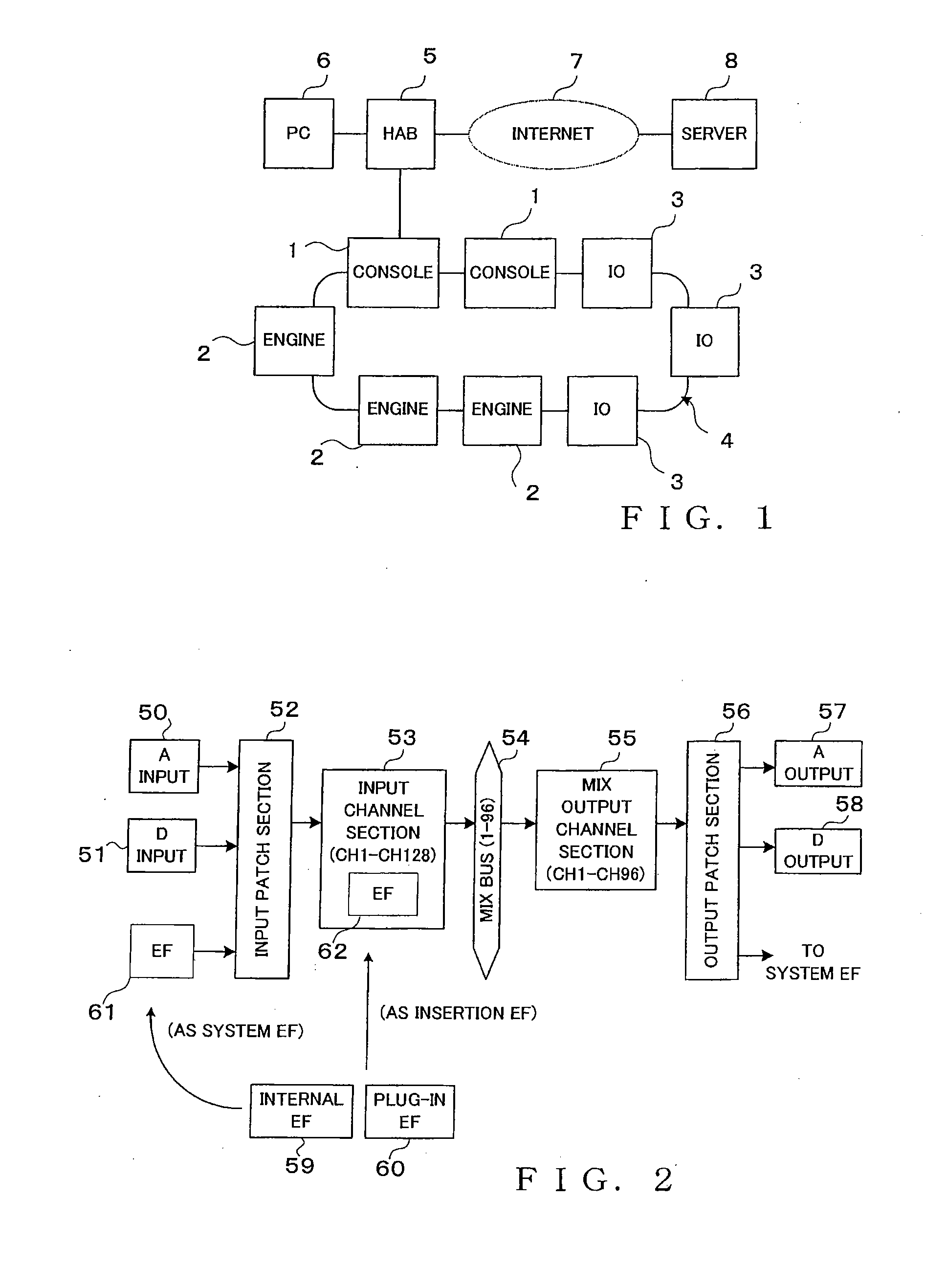
[0026]FIG. 1 is a block diagram explanatory of an example general construction of an embodiment of a mixing system to which is applied the present invention. This mixing system comprises a plurality of system component apparatus (nodes) including a plurality of types of audio signal processing apparatus, such as consoles 1, mixing engines 2 and I / O apparatus 3. Of the system component apparatus, apparatus, such as the consoles 1, mixing engines 2 and I / O apparatus 3, which share later-described audio signal lines (audio signals), will hereinafter be referred to as “audio signal processing apparatus”, to distinguish from other system component apparatus, such as a PC 6, than the audio signal processing apparatus. Namely, the mixing system comprises a group of all of the audio signal processing apparatus interconnected via an audio network and sharing all of the audio signal lines and all of the other system component apparatus (nodes) connected, v...


PUM


Abstract

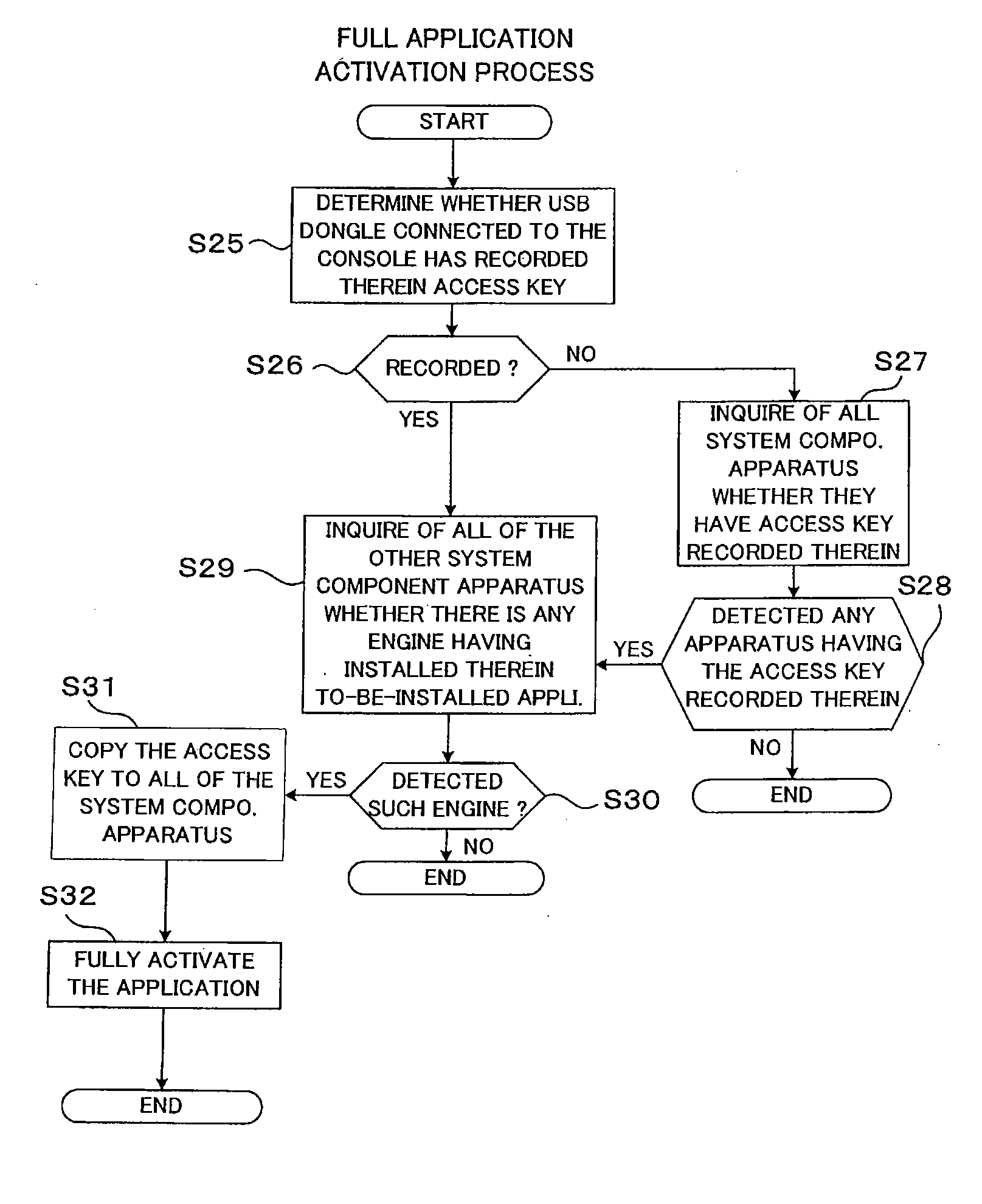
User operates a selection switch to instruct temporary activation of an application. For the application of which the temporary activation has been instructed, a CPU of a console allocates resources necessary for signal processing by a DSP of an engine and for a parameter editing function of the console. In the DSP, a bypass parameter is set to ON. Thus, there is provided a state capable of accepting various parameter setting operation related to the application, but the signal processing based on the application program is prevented from being started in a substantive manner. In response to a full activation instruction of an application via a full activation instruction switch, the bypass parameter is set to OFF, so that audio signal processing based on the application can be started. In this way, preparatory work for setting parameters related to the application can be performed efficiently.

Description

BACKGROUND[0001]The present invention relates to audio signal processing apparatus for performing signal processing on audio signals based on an application program, and more particularly to a technique for controlling activation of an application program.[0002]Heretofore, there have been known digital audio mixers of a type having an effect imparting application program prestored in an internal memory. The prestored application program has to be subjected to license management for purposes like preventing unauthorized use of the application program.[0003]Among the conventionally-known license management techniques for an application program pre-installed in a digital audio mixer is one in accordance with which data of a license (i.e., access key) authorizing activation of the program to be license-managed is purchased via the Internet and the thus-purchased access key is recorded into an internal memory of the mixer, as disclosed, for example, in Japanese Patent Application Laid-op...

Claims


Application Information

Patent Timeline
IPC IPC(8): G06F21/22
CPCH04H60/04G06F21/123
Inventor FUKATA, AYUMINAKAYAMA, KEI
Owner YAMAHA CORP
Learn More