Laser Scanner System And Registration Method Of Point Cloud Data

Active Publication Date: 2018-01-04
KK TOPCON
View PDF21 Cites 10 Cited by
  • Summary
  • Abstract
  • Description
  • Claims
  • Application Information

AI Technical Summary

Benefits of technology

[0015]According to the present invention, the laser scanner system comprises a laser scanner which includes a distance measuring unit for emitting a distance measuring light, receiving a reflected light from an object to be measured, and performing a distance measurement, a scanning unit for rotatably irradiating the distance measuring light, a directional angle detecting unit for detecting an irradiating direction of the distance measuring light, a GNSS device and a control arithmetic unit, and a target which sets a back sight point, wherein the control arithmetic unit has a target scanning mode in which a target scanning is performed over a range including the target and a point cloud data measurement mode in which the distance measuring light is scanned to a measurement range and point cloud data is acquired, and is configured to calculate point cloud data with a global coordinate value and a global coordinate value of the target based on the global coordinate value obtained by the GNSS device, a measurement result obtained by executing the point cloud data measurement mode and a measurement result obtained by executing the target scanning mode. As a result, the laser scanner can be installed at an arbitrary position according to a working environment, a measurement work of an instrument height of the laser scanner or the like can be omitted, the measurement work can be efficiently performed, and the point cloud data as acquired can be easily converted into the global coordinate value.
[0016]Further, according to the present invention, the laser scanner system further comprises a data processing device, wherein the control arithmetic unit is configured to obtain global coordinate values of an installation position of the laser scanner from the GNSS device at a plurality of installation points of the laser scanner respectively, determine a target central position by executing the target scanning mode, and acquire point cloud data by exe

Problems solved by technology

Further, in a case where the object to be measured is a structure such as a building or the like, if a measurement is performed from o

Method used


Image

  • Laser Scanner System And Registration Method Of Point Cloud Data
  • Laser Scanner System And Registration Method Of Point Cloud Data
  • Laser Scanner System And Registration Method Of Point Cloud Data

Examples


Embodiment Construction

[0022]A description will be given below on an embodiment of the present invention by referring to the attached drawings.

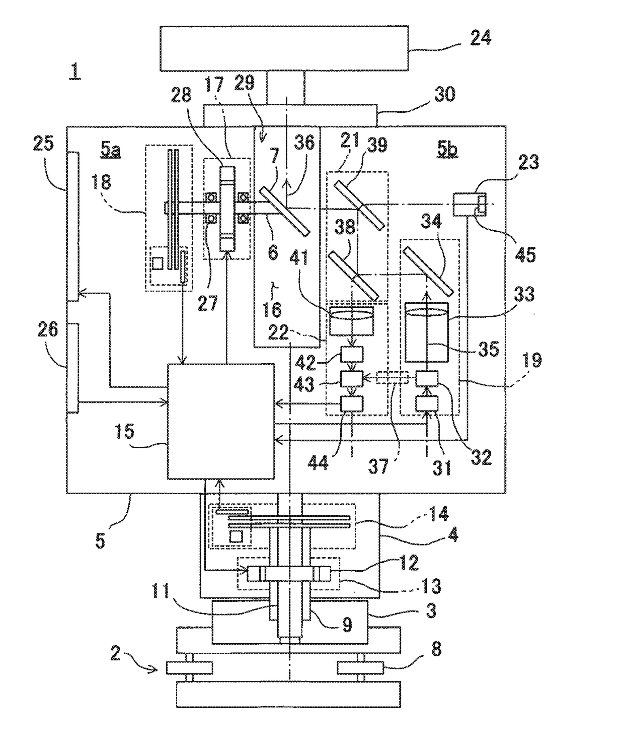
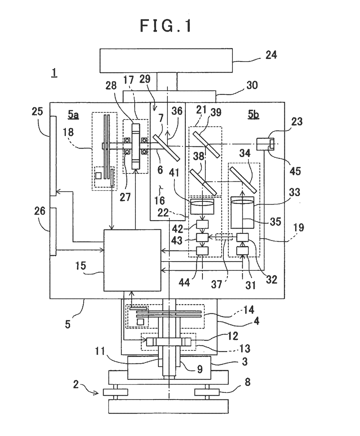
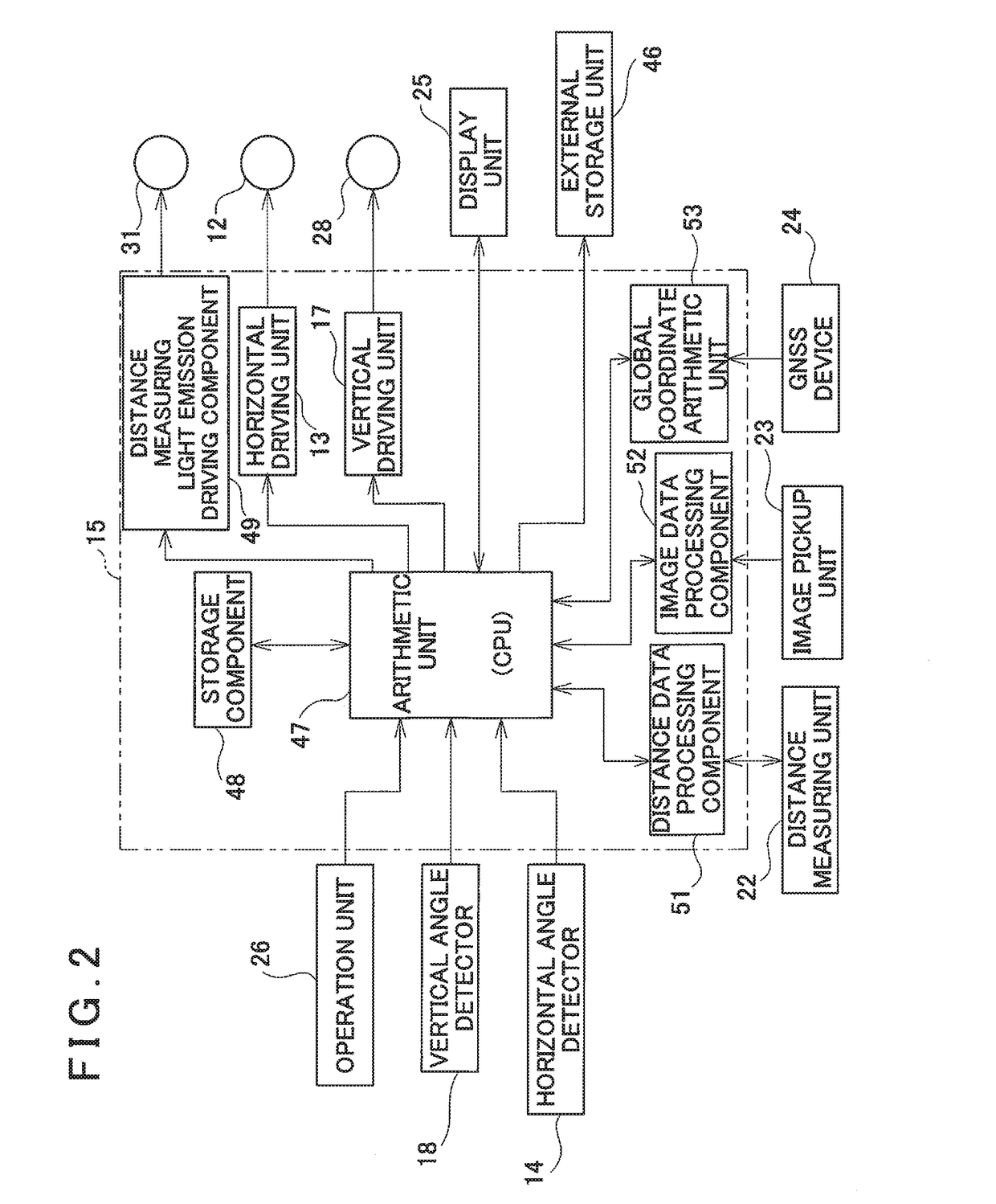
[0023]First, referring to FIG. 1 and FIG. 2, a description will be given on a three-dimensional laser scanner used in the present embodiment.

[0024]As shown in FIG. 1, a laser scanner 1 is installed via a tripod 10 (see FIG. 3). The laser scanner 1 comprises a leveling unit 2 attached on the tripod 10, a base unit 3 provided on the leveling unit 2, a frame unit 5 provided on the base unit 3 via a horizontal rotary unit 4 so as to be rotatable in a horizontal direction and a scanning mirror 7 provided on the frame unit 5 so as to be rotatable around a vertical rotation shaft 6 as a center in a vertical direction (an elevation direction).

[0025]The leveling unit 2 has, e.g., one supporting pin (not shown) and two adjusting screws 8. When the adjusting screws 8 are adjusted so that a tilt sensor (not shown) provided on the frame unit 5 detects a horizontality, a levelin...


PUM


Abstract

The invention provides a laser scanner system, which comprises a laser scanner which includes a distance measuring unit for emitting a distance measuring light, receiving a reflected light, and performing a distance measurement, a scanning unit for rotatably irradiating the distance measuring light, a directional angle detecting unit for detecting an irradiating direction of the distance measuring light, a GNSS device and a control arithmetic unit, and a target which sets a back sight point, wherein the control arithmetic unit has a target scanning mode and a point cloud data measurement mode, and is configured to calculate point cloud data with a global coordinate value and a global coordinate value of the target based on the global coordinate value obtained by the GNSS device, a measurement result obtained by executing the point cloud data measurement mode and a measurement result obtained by executing the target scanning mode.

Description

BACKGROUND OF THE INVENTION[0001]The present invention relates to a laser scanner system which acquires point cloud data, acquires the point cloud data from a plurality of points by the laser scanner and integrates a plurality of point cloud data as point cloud data of the same coordinate system and a registration method of the point cloud data.[0002]As a measuring instrument for acquiring three-dimensional data of an object to be measured, a laser scanner is used. The laser scanner scans a distance measuring light and acquires point cloud data of an object to be measured or a range to be measured. Based on the point cloud data as acquired, a shape and the three-dimensional data of the object to be measured can be determined.[0003]Further, in a case where the object to be measured is a structure such as a building or the like, if a measurement is performed from one direction, point cloud data of a shaded portion cannot be acquired. For this reason, the point cloud data of the object...

Claims


Application Information

Patent Timeline
IPC IPC(8): G01S17/89G01S17/42G01S17/87G01S19/14G01S17/86
CPCG01S17/89G01S19/14G01S17/42G01S17/87G01S7/4817G01S17/86G01C15/002
Inventor KOMEICHI, TAKAHIROYOSHINO, KEN-ICHIROITO, TADAYUKI
Owner KK TOPCON
Why Eureka
Try Eureka