Spinal correction system with multi-stage locking mechanism

a locking mechanism and spine technology, applied in the field of spine correction, can solve the problems of less manageable installation steps and additional parts, and achieve the effect of sufficient “flexion” and facilitate the flexion of the head-body

Inactive Publication Date: 2007-02-22
CAWLEY TRACE R +2
View PDF22 Cites 128 Cited by
  • Summary
  • Abstract
  • Description
  • Claims
  • Application Information

AI Technical Summary

Benefits of technology

[0005] In the preferred embodiment, the head-body includes one or more gaps to facilitate flexion of the head-body as a rotational torque is placed on the cap. The gap or gaps may be horizontal, vertical or other angles relative to the axis of the entrapped rod. With appropriate selection of materials and cross-section, sufficient “flexion” may be established without the need for gaps.
[0006] Tapered threads may be used on the head-body and / or cap to achieve subsequent tightening of the polyaxial screw and rod to a continuous rotational movement. An optional compression-enhancing bushing may be disposed between the rod and the ball-shaped head of the screw. Although the invention is described in conjunction with rod fixation, extensions to rod and plate or plate-only configurations are possible.

Problems solved by technology

One of the deficiencies with existing systems, however, is that the mechanism used to lock the polyaxial screw is different from the mechanism used to lock the rod, thereby requiring additional parts and less manageable installation steps.

Method used


Image

  • Spinal correction system with multi-stage locking mechanism
  • Spinal correction system with multi-stage locking mechanism
  • Spinal correction system with multi-stage locking mechanism

Examples


Embodiment Construction

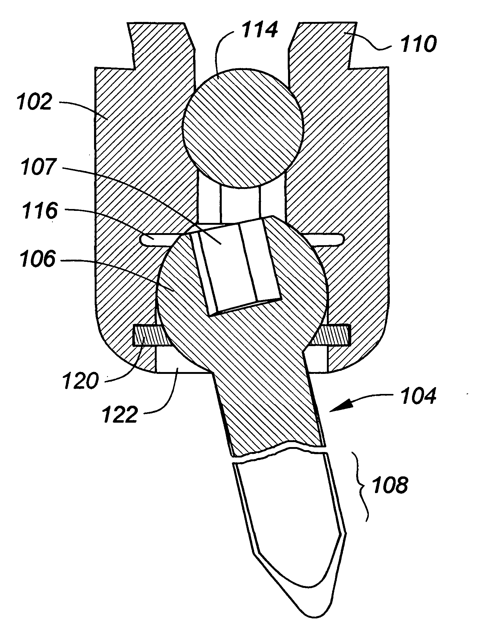
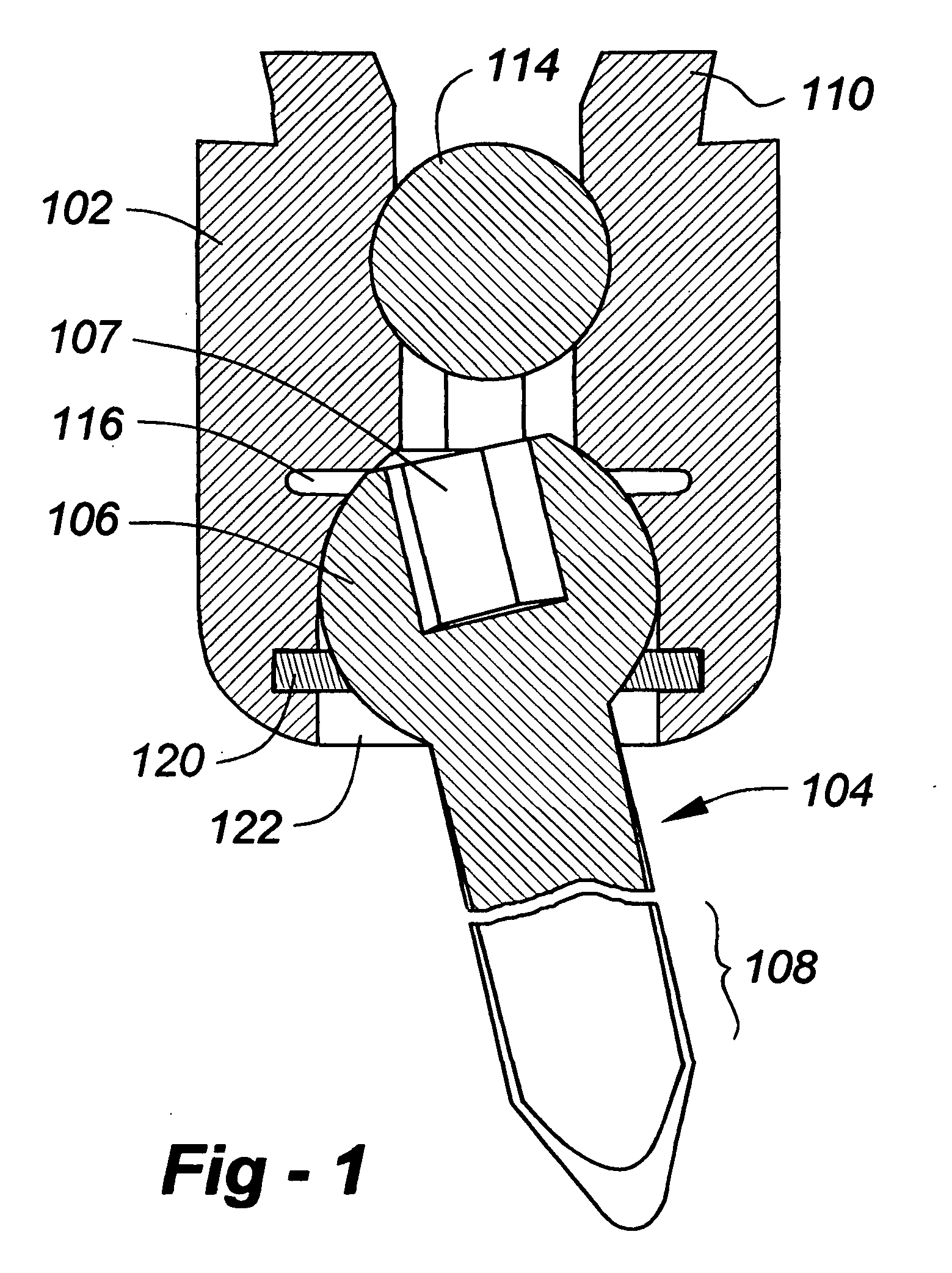
[0014] Broadly, this invention resides in a rod fixation system to treat various spinal conditions, wherein the same fastener is used to lock both a polyaxial screw and a rod in position. Although the invention is described in conjunction with rod fixation, extensions to rod and plate or plate-only configurations are possible.

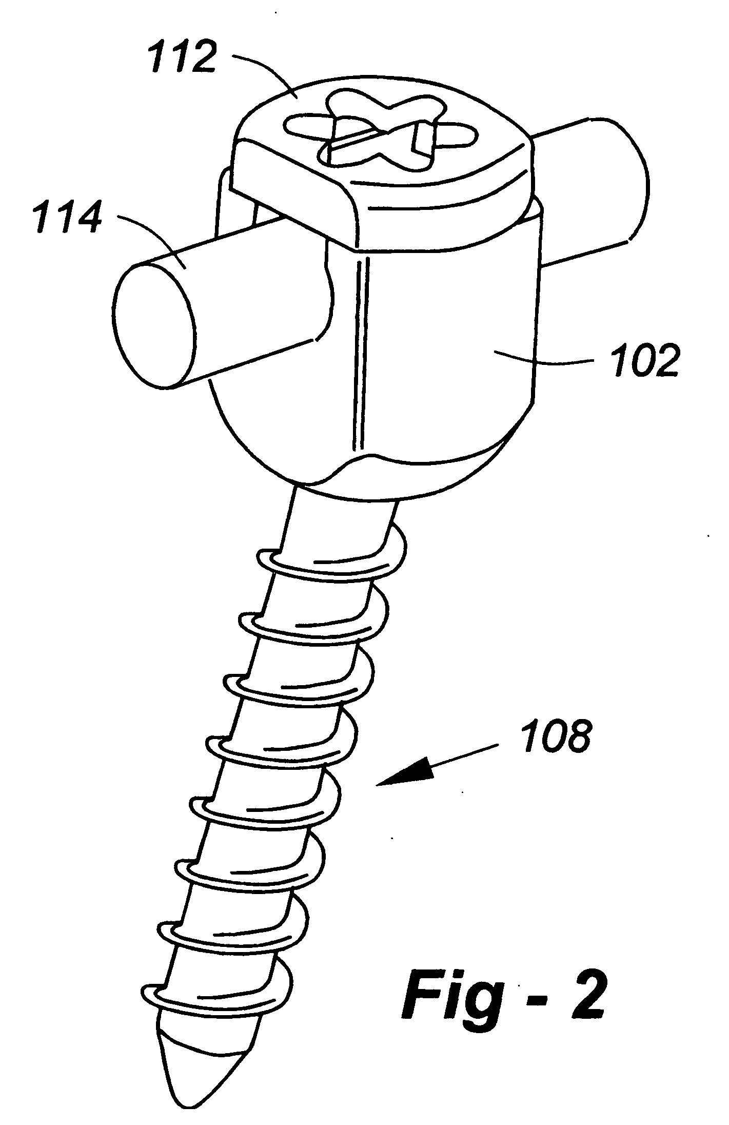
[0015] Reference is now made to FIGS. 1 and 2, which show from a cross-section and oblique view, respectively, a first preferred embodiment of the invention utilizing three primary components, namely, a head-body 102, a polyaxial screw 104, and a cap 112 (not shown in FIG. 1). The polyaxial screw 104 includes a proximal hemispherical head 106 and a distal threaded portion 108. The ball portion of the screw includes some type of turning aperture, such as hex depression 107. The screw 104 is held in position within the head-body 102 through bushing 120 and fastener 122, facilitating assembly from the bottom. The fastener 122 may be threaded, press fit or otherwi...


PUM


Abstract

In a rod fixation system of the type used to treat various spinal conditions, the same fastener is used to lock both a polyaxial screw and a rod in position. A spinal correction device according to the invention, adapted for use with a rod and a polyaxial screw having a ball-shaped head and a threaded end, comprises a head-body and a cap. The head-body includes a lower internal cavity to receive the ball-shaped head of the screw, an upper bore to receive a fixation rod therethrough, and an upper end configured to receive the cap. The head-body and the cap are configured such that a first rotation of the cap locks the polyaxial screw in position, and a second rotation of the cap locks the rod in position. In the preferred embodiment, the head-body includes one or more gaps to facilitate flexion of the head-body as a rotational torque is placed on the cap. The gap or gaps may be horizontal, vertical or other angles relative to the axis of the entrapped rod.

Description

REFERENCE TO RELATED APPLICATION [0001] This application claims priority from U.S. Provisional Patent Application Ser. No. 60 / 691,708, filed Jun. 17, 2005, the entire content of which is incorporated herein by reference.FIELD OF THE INVENTION [0002] This invention relates generally to spinal correction and, in particular, to a system incorporating a multi-stage locking mechanism. BACKGROUND OF THE INVENTION [0003] There are many spine-related conditions, such as scoliosis, which require multi-level correction / fixation. Numerous plate and rod systems are available for this purpose, many of which have received patent protection. One of the deficiencies with existing systems, however, is that the mechanism used to lock the polyaxial screw is different from the mechanism used to lock the rod, thereby requiring additional parts and less manageable installation steps. SUMMARY OF THE INVENTION [0004] Broadly, this invention resides in a rod fixation system to treat various spinal condition...

Claims


Application Information

Patent Timeline
Patent Type & Authority Applications(United States)
IPC IPC(8): A61F2/30
CPCA61B17/7032A61B17/7035A61B17/7037
Inventor CAWLEY, TRACE R.PEPPER, JOHNBLAKE, DORIS M.
Owner CAWLEY TRACE R
Why Eureka
Try Eureka