Ankle support with splint and method of using same

a technology of splint and support, applied in the field of orthopaedic supports, can solve the problems of sacrificing comfort and mobility for wearers, too much stability, and less lateral stability, and achieve the effect of facilitating the positioning of the splint and preventing inversion

Inactive Publication Date: 2014-01-07
3M INNOVATIVE PROPERTIES CO
View PDF68 Cites 5 Cited by
  • Summary
  • Abstract
  • Description
  • Claims
  • Application Information

AI Technical Summary

Benefits of technology

[0009]According to one embodiment, the splint has an undulating profile configured to conform to the wearer's calf, medial malleolus / subcutaneous bursa, and arch. Thus, the splint may have respective curvatures for conforming to each of the calf, medial malleolus / subcutaneous bursa, and the arch. The portion of the splint configured to conform to the arch may have varying configurations. For example, the end of the splint may be tapered. Or, the splint may have a hinged portion that is configured to provide rotation for facilitating flexion of the wearer's ankle.
[0014]Embodiments of the present invention may provide many advantages. For instance, the orthopedic support may be an ankle support capable of being used during everyday activities and for treatment of acute ankle injuries. The ankle support may include a splint that is configured to be positioned on only a medial side of the ankle and prevent inversion that may lead to ankle injuries. In particular, the curvature of the ankle support is configured to conform to the ankle so as to provide comfort, while at the same time providing support and resistance to inversion. Moreover, the splint may be ambidextrous and may be used on the medial sides of both the left and right ankles. The ankle support may incorporate an adjustable tension system that allows a wearer to achieve a desired level of support. In addition, the ankle support may include a strapping system or pocket to facilitate positioning of the splint adjacent to the wearer's ankle.

Problems solved by technology

For instance, splints for treating less serious injuries may provide less lateral stability and, thus, more mobility.
While splints may be used to provide lateral stability, too much stability may sacrifice comfort and mobility for the wearer.

Method used


Image

  • Ankle support with splint and method of using same
  • Ankle support with splint and method of using same
  • Ankle support with splint and method of using same

Examples


Embodiment Construction

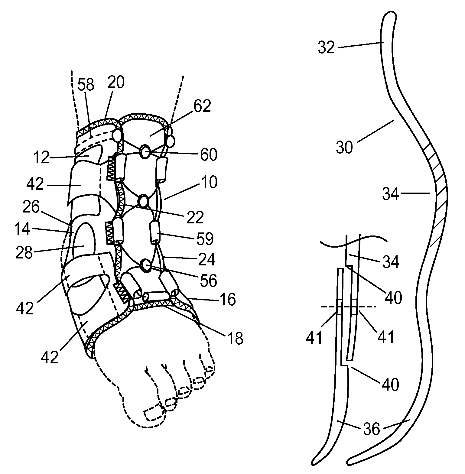
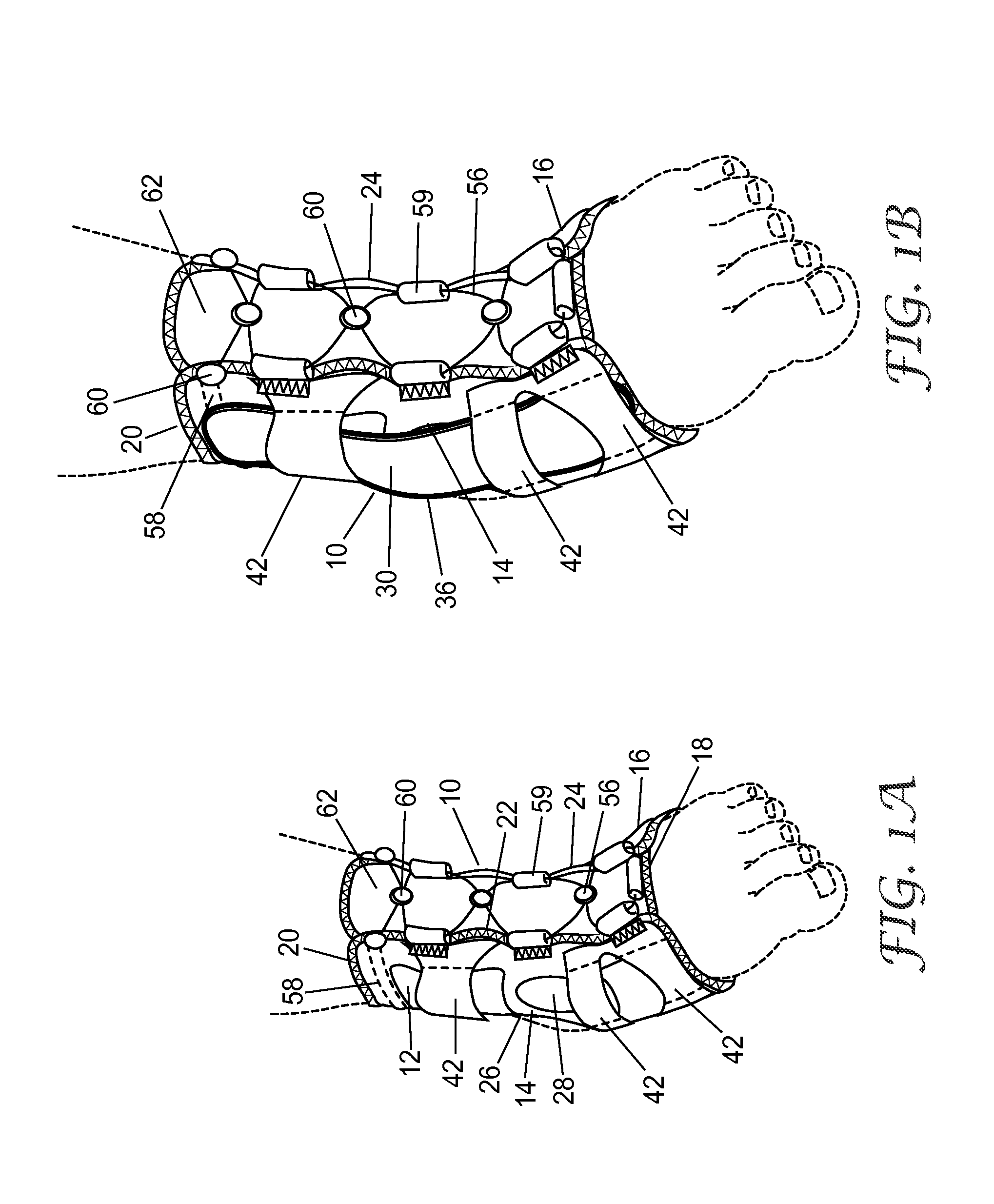
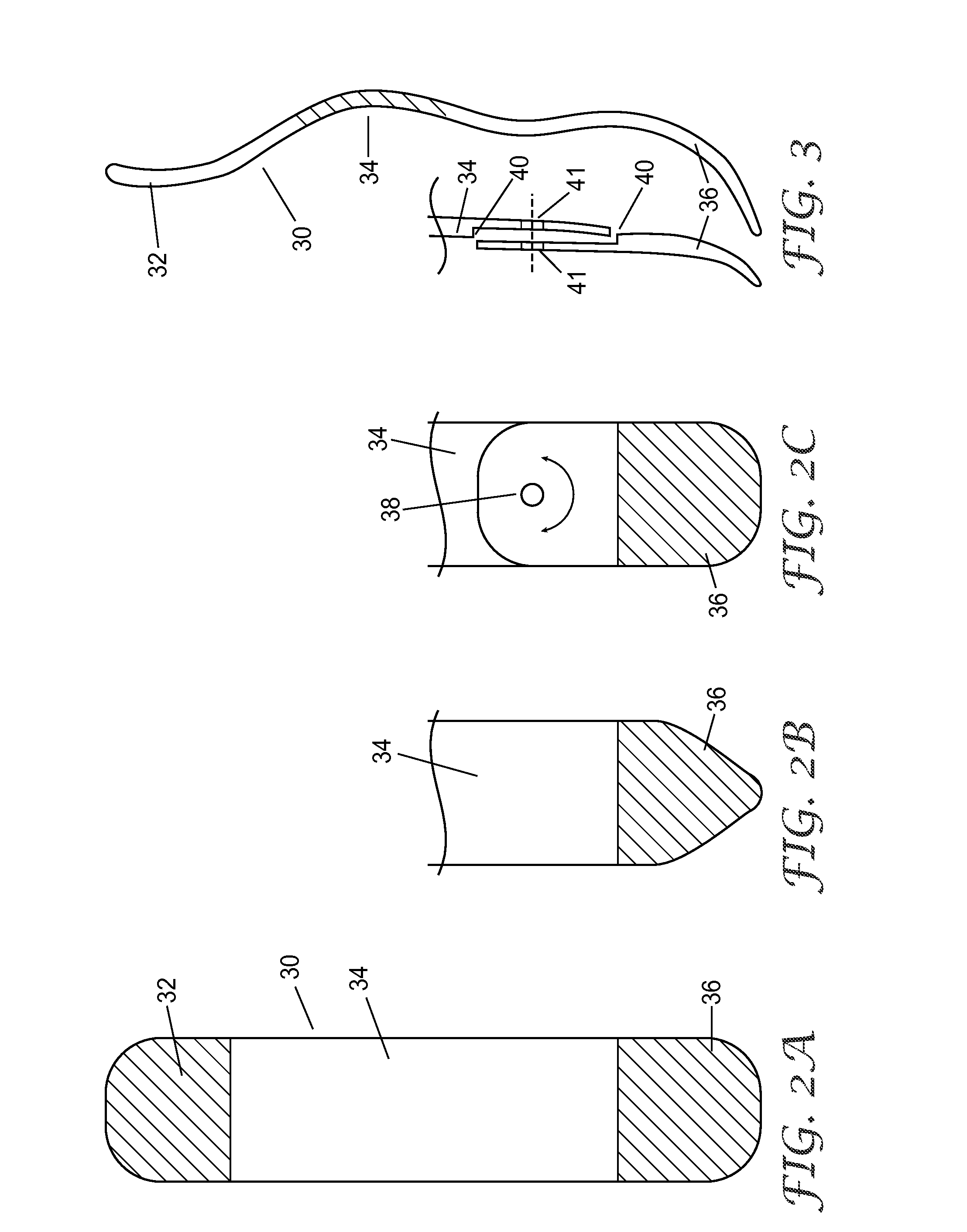
[0023]The present invention now will be described more fully hereinafter with reference to the accompanying drawings, in which some, but not all embodiments of the invention are shown. Indeed, the invention may be embodied in many different forms and should not be construed as limited to the embodiments set forth herein; rather, these embodiments are provided so that this disclosure will satisfy applicable legal requirements. Like numbers refer to like elements throughout.

[0024]Generally, the present invention provides an orthopedic support that includes a sheet of flexible material for wrapping about and conforming to a portion of a wearer's anatomy. The orthopedic support includes a splint configured to provide lateral stability for supporting the wearer's joint. In addition, the orthopedic support may include an adjustable tension system for securing the orthopedic support on a wearer's limb. Although reference is made to an ankle support below, the orthopedic support could be ad...


PUM


Abstract

According to one embodiment, an orthopedic support for supporting a portion of a wearer's anatomy is provided. For example, the orthopedic support may be an ankle brace comprising a sheet of flexible material configured to at least partially enclose a wearer's ankle and a splint coupled to the sheet of material. The splint is configured to be positioned on a medial side of the wearer's ankle when the sheet of material is secured on the wearer's ankle and includes an undulating profile configured to conform to at least a portion of the medial side of the wearer's ankle and resist inversion of the ankle.

Description

CROSS REFERENCE TO RELATED APPLICATIONS[0001]This application is a national stage filing under 35 U.S.C. 371 of PCT / US2009 / 043310, filed May 8, 2009, which claims priority to Provisional Application No. 61 / 127,604, filed May 14, 2008, the disclosure of which is incorporated by reference in its / their entirety herein.BACKGROUND OF THE INVENTION[0002]1. Field of the Invention[0003]The present invention is related to the field of orthopedic supports, and more particularly, to orthopedic supports having a splint for supporting a portion of a wearer's anatomy.[0004]2. Description of Related Art[0005]Stays or splints are commonly employed with orthopedic supports to stabilize or immobilize a joint of a wearer. Splints may be rigid for providing more support or relatively flexible for providing mobility, and frequently splints are used to support the medial and lateral sides of the joint. For instance, the medial and lateral sides of the ankle or knee commonly need to be supported due to th...

Claims


Application Information

Patent Timeline
Patent Type & Authority Patents(United States)
IPC IPC(8): A61F5/00
CPCA61F5/0585A61F5/0127A61F5/0111
Inventor WEAVER, II, EDWARD L.ELROD, JOHN R.
Owner 3M INNOVATIVE PROPERTIES CO
Why Eureka
Try Eureka