Rotary fluid machine

Active Publication Date: 2014-05-22
GREJSTOUN TEKNOLODZHIZ PTI LTD
View PDF7 Cites 5 Cited by
  • Summary
  • Abstract
  • Description
  • Claims
  • Application Information

AI Technical Summary

Benefits of technology

[0114]In one embodiment the sealing system comprise at least two sealing bands juxtaposed face to face, each sealing band being provided with a plurality of slots to facilitate flexing of the sealing bands, and wherein the sealing bands and slots are arranged

Problems solved by technology

Machine performance and reliability is also substantially affected by the nature of the fluid passing through the machine.
For

Method used


Image

  • Rotary fluid machine
  • Rotary fluid machine
  • Rotary fluid machine

Examples


Embodiment Construction

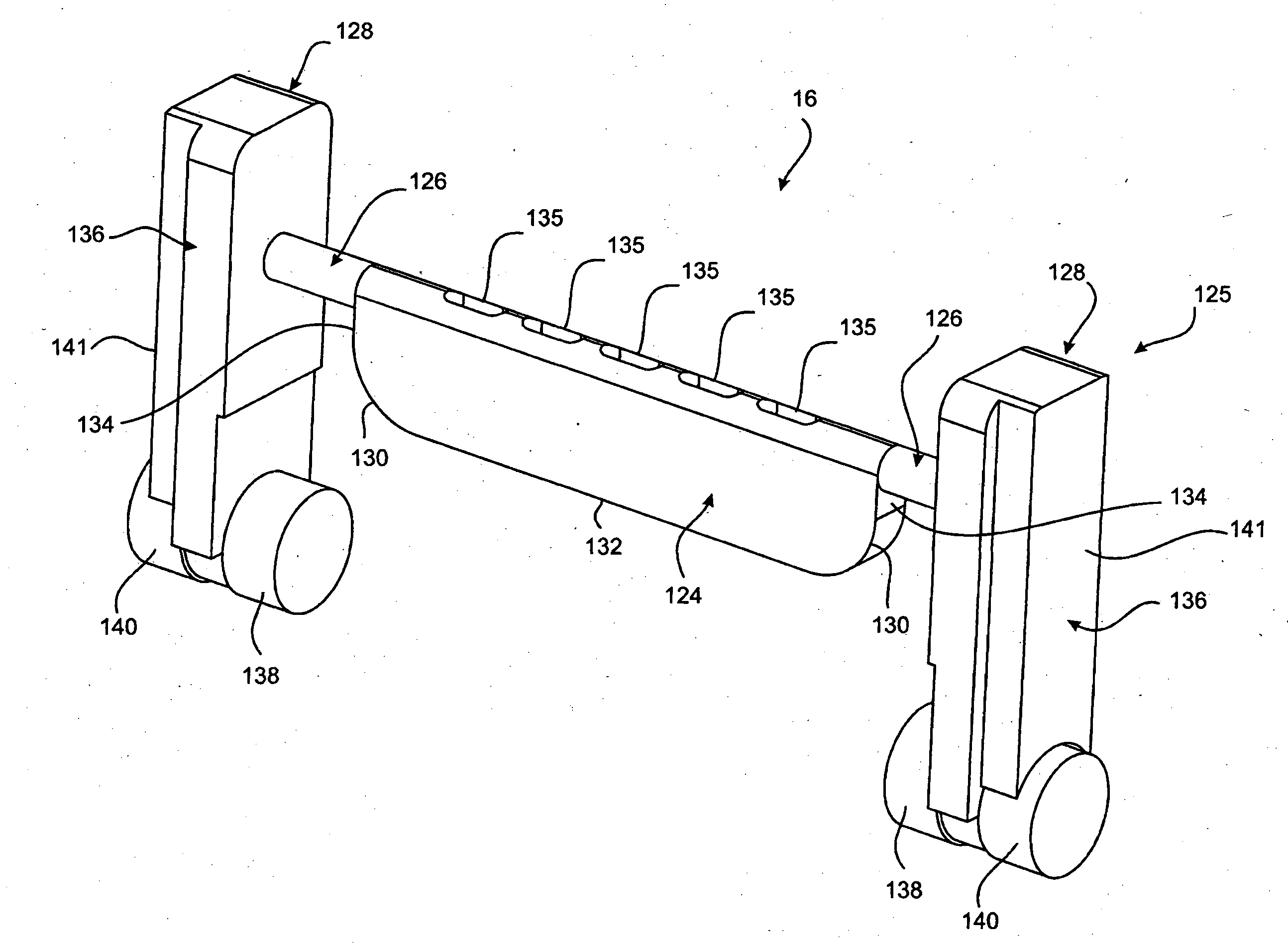
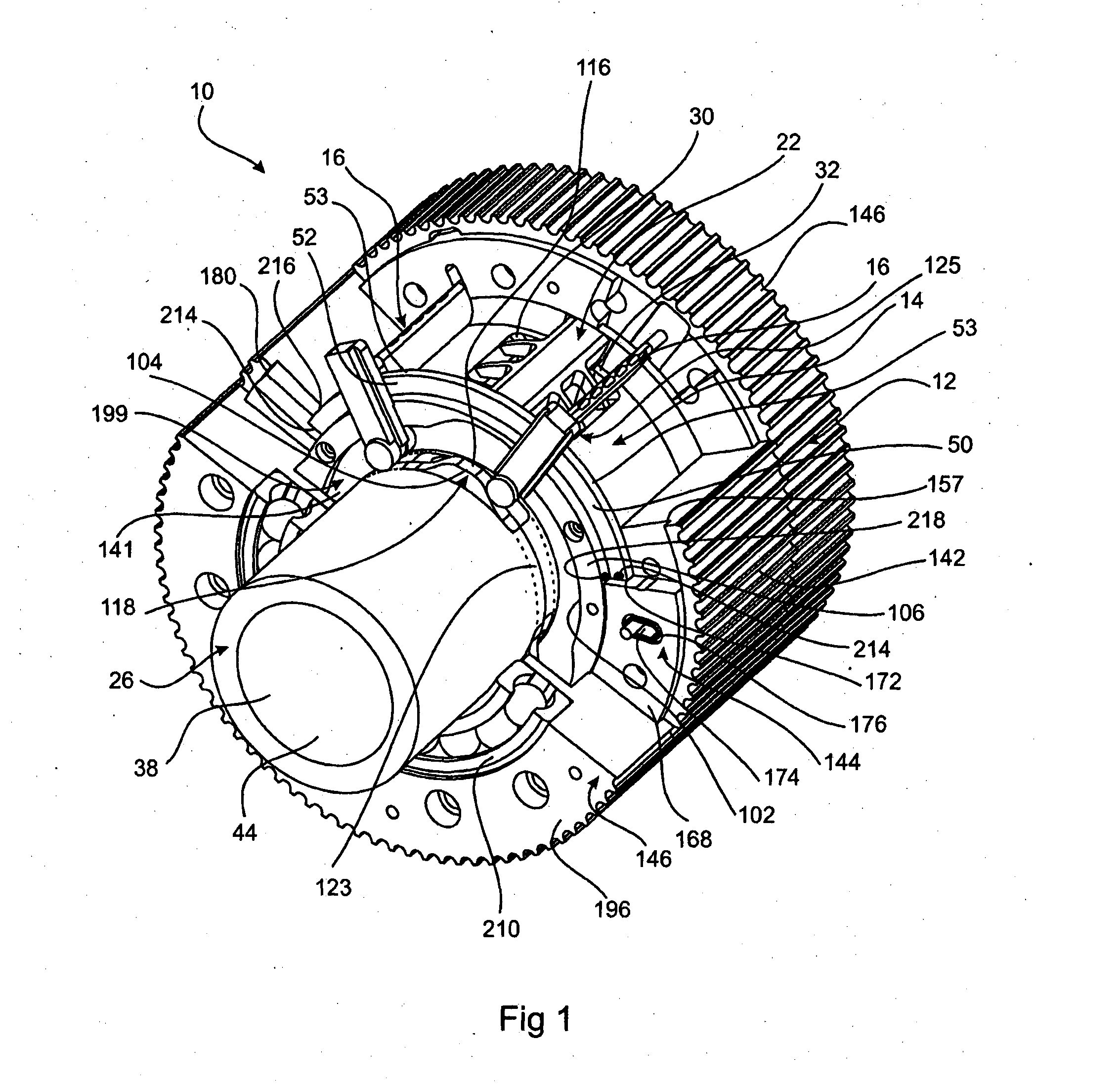
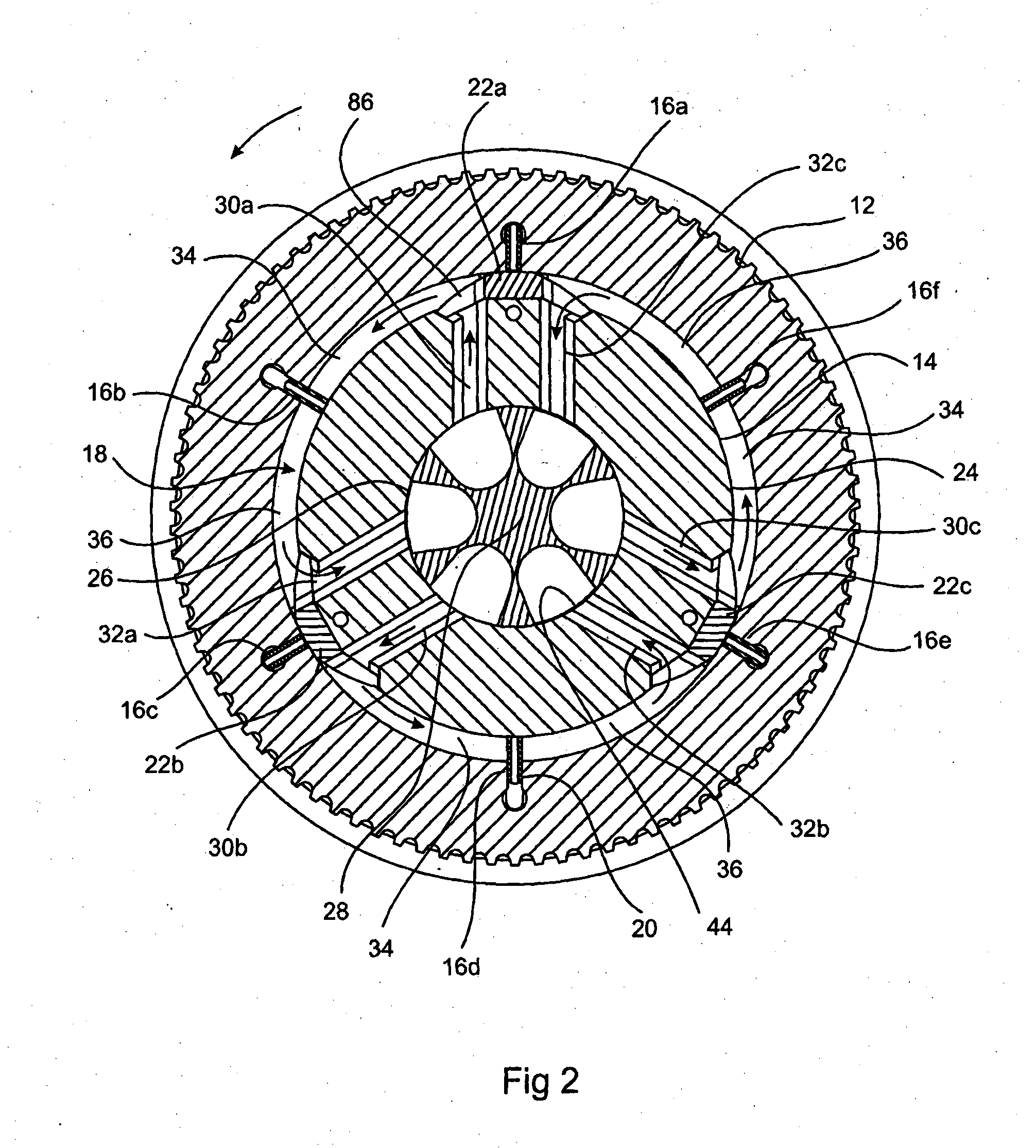
[0169]Referring to the accompanying drawings and in particular FIGS. 1-3, an embodiment of a rotary fluid machine 10 comprises a first body 12, a second body 14, and a plurality of gates 16a-16f (hereinafter referred to in general as “gate(s) 16”). In this embodiment, the first body 12 is a rotor while the second body 14 is a stator. The rotor 12 and stator 14 are rotatable relative to each other and arranged one inside the other to define a working chamber 18 there between. Gates 16 are supported in radial gate slots 20 formed in the rotor 12 and cyclically extend from and retract into the gate slots 20 as the rotor 12 rotates about stator 14. A plurality of demountable lobes 22a-22c (hereinafter referred to in general as “lobe(s) 22”) is supported on an outer circumferential surface 24 of stator 14. The surface 24 forms a surface of the working chamber 18. As rotor 12 rotates the gates 16 wipe across the outer circumferential surface 24 and lobes 22. This causes displacement of fl...


PUM


Abstract

A rotary fluid machine 10 has a rotor 12, a stator 14, and a plurality of gates. The rotor 12 and stator 14 are rotatable relative to each other and arranged one inside the other to define a working chamber 18 there between. Gates 16 are supported in radial gate slots 20 formed in the rotor 12 and cyclically extend from and retract into the gate slots 20 as the rotor 12 rotates about stator 14. A plurality of demountable lobes is supported on an outer circumferential surface 24 of stator 14. The surface 24 forms a surface of the working chamber 18. Circumferential surface 24 is composed of an intermediate surface 48 which extends in an axial direction and opposite curved surfaces 46. The gate 16 has opposite rounded corners 130 separated by an axial planar surface 132. The shape and configuration of the gate 16 and corresponding is made to match that of the outer circumferential surface 24 so that when the axial surface 132 lies substantially adjacent and parallel to intermediate surface 48 each of the curved surfaces 130 lie closely adjacent to and substantially parallel with the concavely curved surfaces 46.

Description

CROSS-REFERENCE TO RELATED APPLICATIONS[0001]This application is a continuation of and claims priority to International Patent Application No. PCT / AU2012 / 000822 filed Jul. 6, 2012, which claims priority to U.S. Provisional Patent Application No. 61 / 505,625 filed Jul. 8, 2011 and U.S. Provisional Patent Application No. 61 / 608,844 filed Mar. 9, 2012, the entire content of each of which is hereby fully incorporated by reference.FIELD OF THE INVENTION[0002]The present invention relates to a rotary fluid machine, and in particular, but not exclusively to a rotary fluid machine that may be operated as either a pump or a motor.BACKGROUND OF THE INVENTION[0003]One type of rotary fluid machine comprises a rotor and a stator which together defined a working chamber. A number of lobes are formed on one of the rotor and the stator, with a plurality of gates being supported by the other. Inlet and outlet ports are provided on opposite sides of each lobe to allow fluid to flow into and out of the...

Claims


Application Information

Patent Timeline
IPC IPC(8): F01C1/356
CPCF04C2/3566F04C2240/10F04C2240/20F04C2240/603F01C21/0809F01C21/0836F01C21/106F01C21/108F01C1/348F04C2/348F01C1/3566
Inventor WHEELER, DARYLERWIN, JUSTIN WADEBURNS, SR., TIMOTHY DONALD
Owner GREJSTOUN TEKNOLODZHIZ PTI LTD
Why Eureka
Try Eureka