
Intrinsic stability in a total hip stem

a total hip and stem technology, applied in the field of prosthetic hip systems, can solve the problems of increased post-operative pain, premature loosening, and dislocation of the hip joint, and achieve the effects of improving post-operative stability, improving post-operative pain, and improving stability

Inactive Publication Date: 2007-02-22
ENCORE MEDICAL ASSET CORP
View PDF99 Cites 30 Cited by
  • Summary
  • Abstract
  • Description
  • Claims
  • Application Information

AI Technical Summary

Problems solved by technology

However, the interface between the bone, the cement and the implant may not be as strong as the cementless system and may result in premature loosening as compared to the cementless system.
Specifically in cementless total hip arthroplasty, dislocation of the hip joint has been and continues to be a problem.
As the femoral offset increases, the potential for increased torsional forces placed on the stem-bone interface likewise increases, and the potential for the stem loosening increases, resulting in increased post-operative pain, disability and an increased risk that additional revision surgery may be necessary.
However, this device is disadvantageous in that the device is unable to withstand the increased torsional loads that may be placed on the device due to an increase in the lateral offset and to the frictional forces acting tangentially on the bone-implant interface.
Torsional forces are disadvantageous in that over time they may cause loosening of the implant from the bone.
However, this device is disadvantageous because it lacks the structure necessary to contact the posterior calcar wall and the anterior cortex of the femur permitting solid contact with cortical bone.
Thus, torsional forces may not be resisted.

Method used


Image

  • Intrinsic stability in a total hip stem
  • Intrinsic stability in a total hip stem
  • Intrinsic stability in a total hip stem

Examples


Embodiment Construction

[0054] For the purposes of promoting an understanding of the principles in accordance with the invention, reference will now be made to the embodiments illustrated in the drawings and specific language will be used to describe the same. It will nevertheless be understood that no limitation of the scope of the invention is thereby intended. Any alterations and further modifications of the inventive features illustrated herein, and any additional applications of the principles of the invention as illustrated herein, which would normally occur to one skilled in the relevant art and having possession of this disclosure, are to be considered within the scope of the invention claimed.

[0055] Before the present device and methods are disclosed and described, it is to be understood that this invention is not limited to the particular configurations, process steps, and materials disclosed herein as such configurations, process steps, and materials may vary somewhat. It is also to be understo...


PUM


Abstract

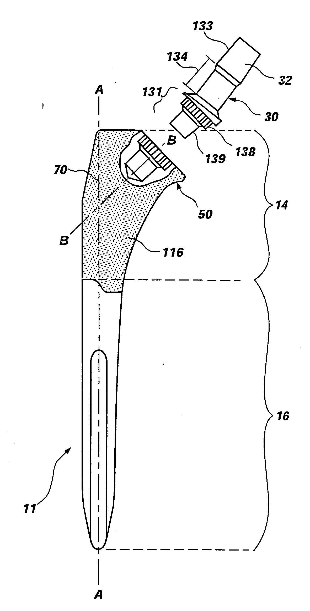
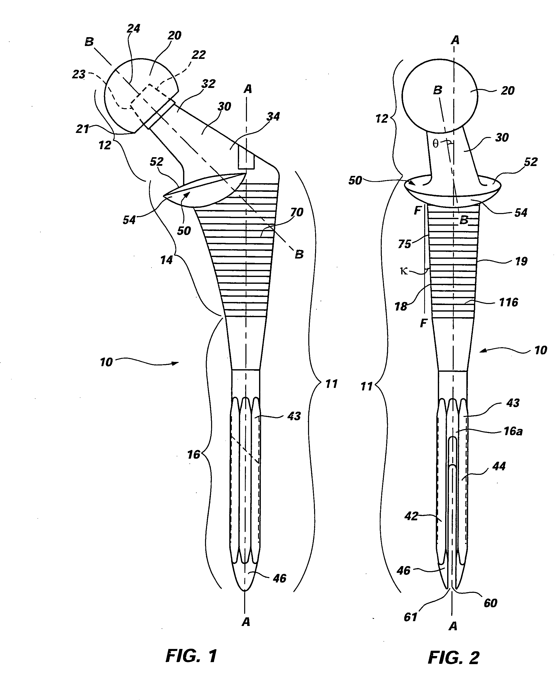
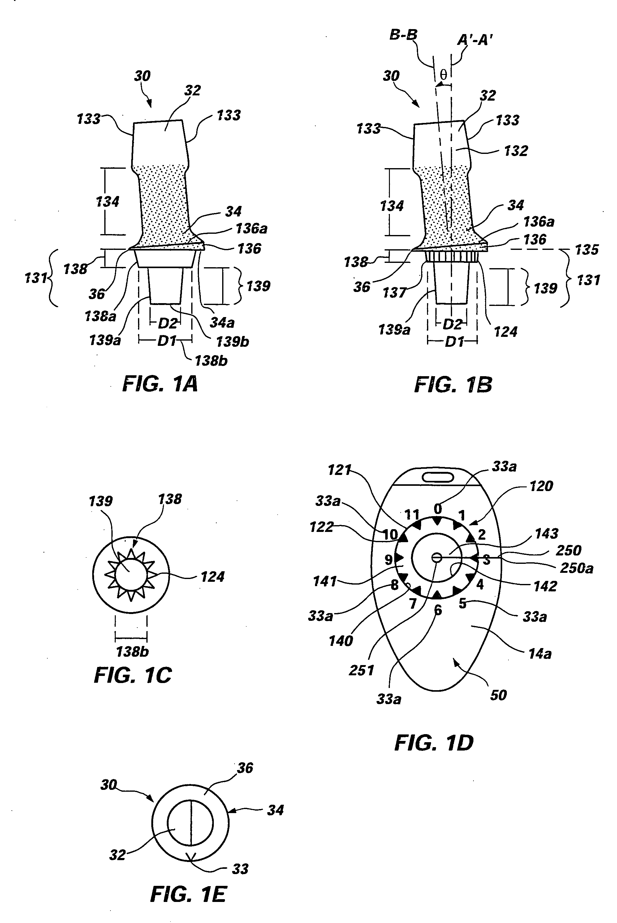
A prosthetic device and method of using the device is disclosed. The device may include a bushing insert, a femoral head component, a neck component that may be either integral or modular, and a stem component having a proximal body portion and a distal portion. The proximal body portion may include such features as a recess for receiving a portion of the modular neck, a proximal conical flare having a bottom surface with a rounded contour, an anterior metaphyseal tapering flare, as well as other features. The distal portion may include a coronal slot, a sagittal slot, a helical slot, or a combination thereof. The above features may be provided for increasing the intrinsic stability of the device and for resisting torsional loads placed on the device.

Description

CROSS-REFERENCE TO RELATED APPLICATIONS [0001] This application is a continuation of co-pending U.S. patent application Ser. No. 10 / 405,065, filed Mar. 31, 2003, entitled “INTRINSIC STABILITY IN A TOTAL HIP STEM,” which claims the benefit of U.S. Provisional Application No. 60 / 442,188, filed Jan. 22, 2003. [0002] Co-pending U.S. patent application Ser. No. 10 / 405,065 is a continuation-in-part application of U.S. patent application Ser. No. 10 / 244,149, filed Sep. 13, 2002, entitled “DIFFERENTIAL POROSITY PROSTHETIC HIP SYSTEM,” which claims the benefit of U.S. Provisional Application No. 60 / 372,390, filed Apr. 12, 2002. [0003] U.S. patent application Ser. No. 10 / 405,065, is a continuation-in-part application of U.S. patent application Ser. No. 09 / 505,876, filed Feb. 17, 2000, entitled “MODULAR NECK FOR FEMUR REPLACEMENT SURGERY,” now U.S. Pat. No. 6,464,728, which is a continuation-in-part application of U.S. patent application Ser. No. 09 / 059,698, filed Apr. 14, 1998, now abandoned....

Claims


Application Information

Patent Timeline
Patent Type & Authority Applications(United States)
IPC IPC(8): A61F2/32A61FA61F2/00A61F2/30A61F2/36A61F2/46
CPCA61F2/30767A61F2/36A61F2/3609A61F2/3662A61F2/367A61F2/3676A61F2002/30011A61F2002/30013A61F2002/30112A61F2002/30125A61F2002/30171A61F2002/30214A61F2002/30321A61F2002/30322A61F2002/30332A61F2002/30341A61F2002/30345A61F2002/30347A61F2002/30377A61F2002/30574A61F2002/30604A61F2002/30606A61F2002/30616A61F2002/30714A61F2002/30795A61F2002/30813A61F2002/3082A61F2002/30906A61F2002/3611A61F2002/3625A61F2002/3631A61F2002/365A61F2002/3652A61F2002/3656A61F2002/3696A61F2002/4631A61F2002/4658A61F2220/0033A61F2230/0004A61F2230/0008A61F2230/005A61F2230/0067A61F2250/0023A61F2250/0024A61F2250/0025A61F2250/0026A61F2250/0089A61F2310/00023A61F2310/00029A61F2/30A61F2/389A61F2/4014A61F2/4059A61F2002/30065A61F2002/30367A61F2002/30339A61F2002/3071A61F2002/3054A61F2002/30594
Inventor MURRAY, IAN P.
Owner ENCORE MEDICAL ASSET CORP
Learn More