Methods and apparatus for nuclear tomo-cardiology scanning

a tomo-cardiology and nuclear technology, applied in the field of medical imaging systems, can solve the problems of difficult image review/evaluate, not providing the necessary image information, and less than optimal imaging conditions

Inactive Publication Date: 2007-03-08
GE MEDICAL SYST ISRAEL
View PDF11 Cites 26 Cited by
  • Summary
  • Abstract
  • Description
  • Claims
  • Application Information

AI Technical Summary

Problems solved by technology

If a patient is off-center, the image may be difficult to review / evaluate and may not provide the necessary image information to perform a proper diagnosis.
This process can lead to less than optimal imaging conditions because it may be difficult for an operator to accurately determine when a patient is properly aligned within the scanner.
Accordingly, less than optimal images may result.
Additionally, multiple manual adjustments may be needed, thereby adding time to the scanning process.
Further, the scanner may be positioned such that viewing positioning adjustments may be almost impossible, for example, if the detector side of the scanner is close to a wall.
However, even with the defined default positions, because of differences in patient size, scanner configurations, etc., manual adjustment is often still needed to accommodate each patient and align the patient within the scanner.

Method used


Image

  • Methods and apparatus for nuclear tomo-cardiology scanning
  • Methods and apparatus for nuclear tomo-cardiology scanning
  • Methods and apparatus for nuclear tomo-cardiology scanning

Examples


Embodiment Construction

[0015] As used herein, an element or step recited in the singular and proceeded with the word “a” or “an” should be understood as not excluding plural elements or steps, unless such exclusion is explicitly recited. Furthermore, references to “one embodiment” of the present invention are not intended to be interpreted as excluding the existence of additional embodiments that also incorporate the recited features.

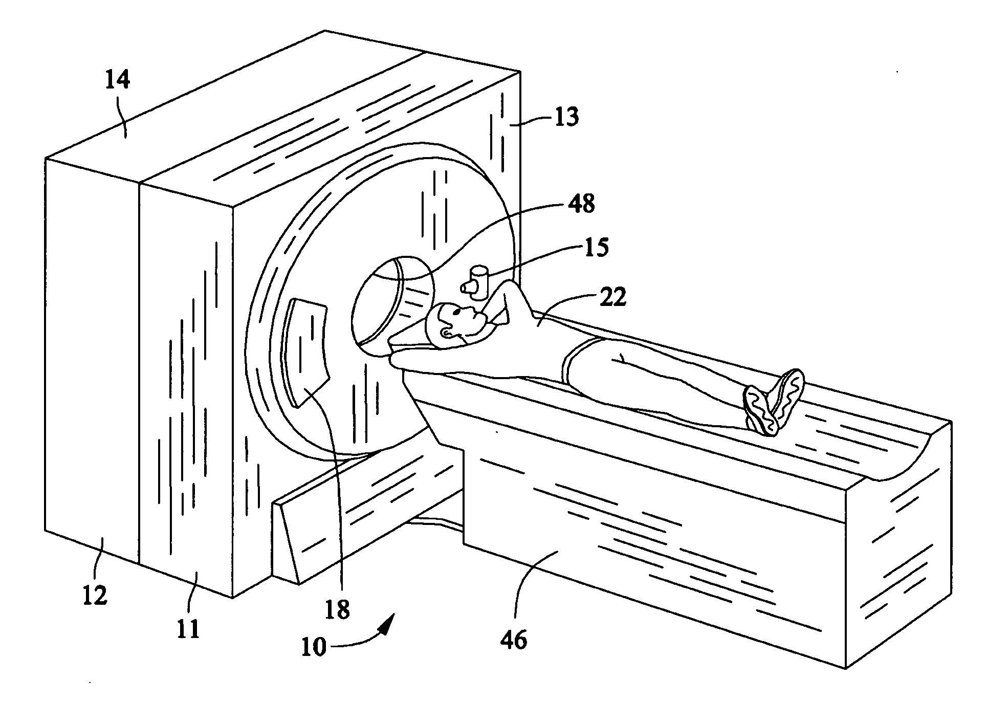
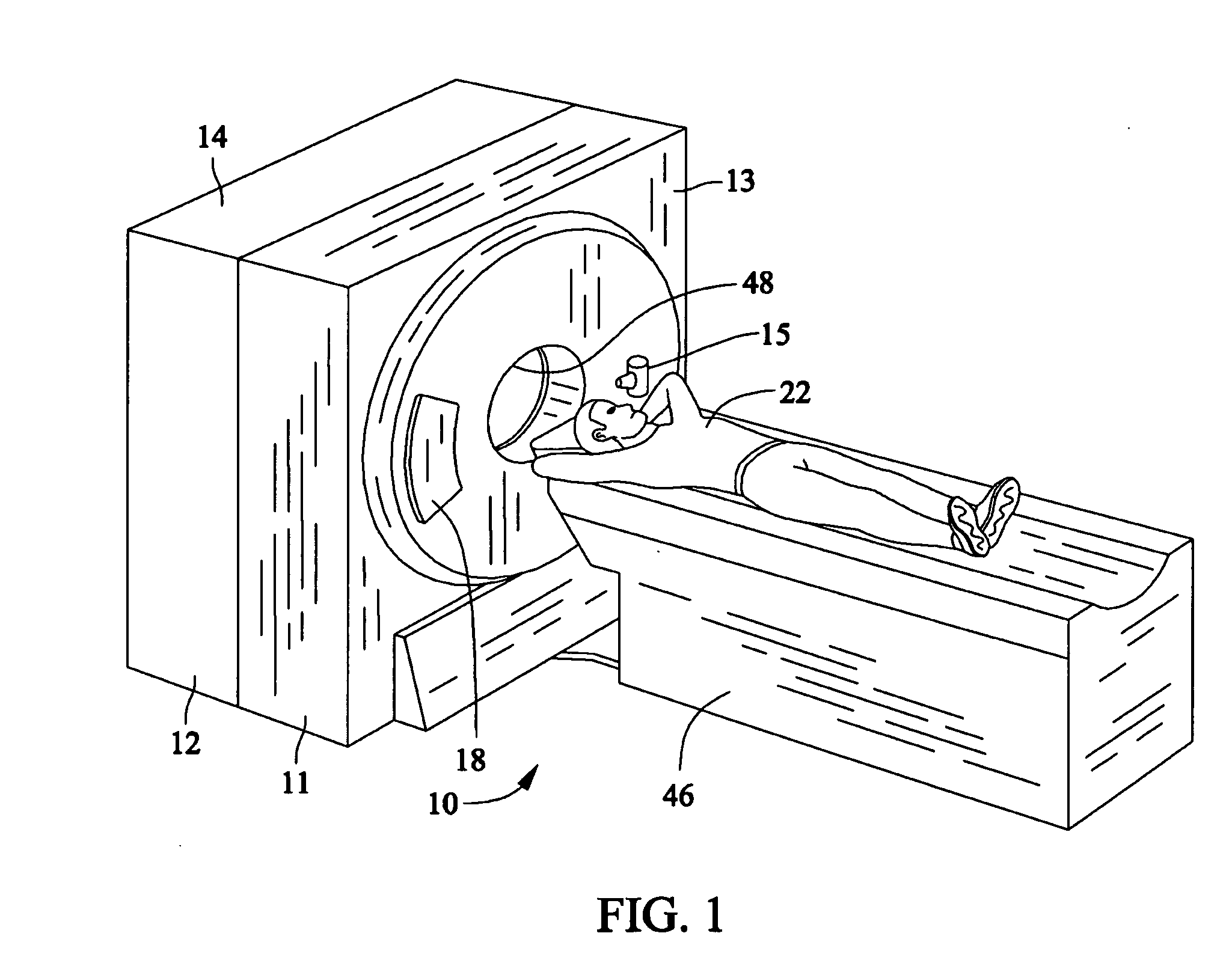
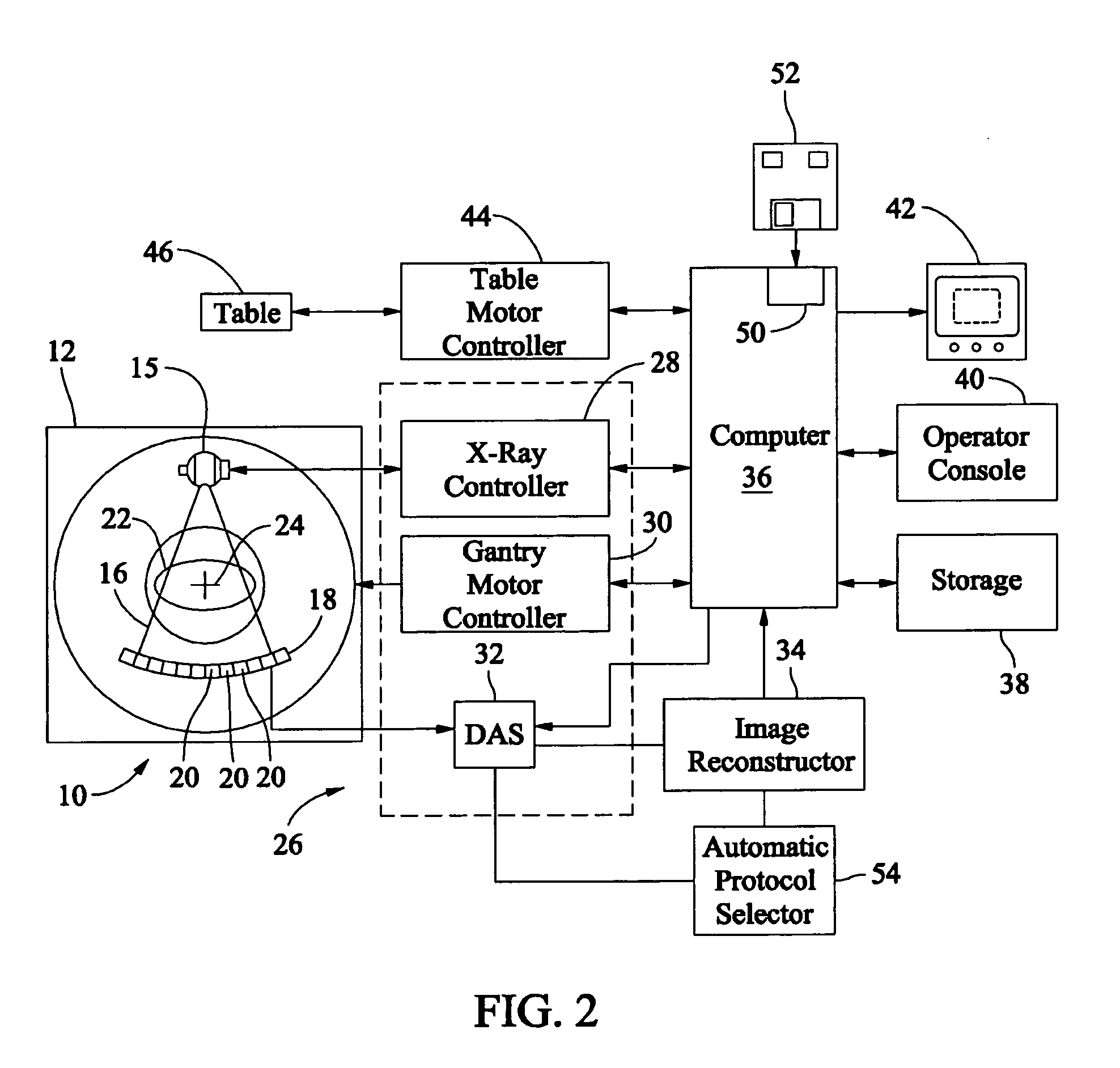
[0016]FIG. 1 is a perspective view of an exemplary imaging system 10 in connection with which various embodiments of the invention may be implemented and operated. FIG. 2 is a schematic block diagram of the imaging system 10 (shown in FIG. 1). Referring now to FIGS. 1 and 2, in an exemplary embodiment, the imaging system 10 is a multi-modal imaging system and includes a first modality unit 11 and a second modality unit 12. The modality units 11 and 12 enable the system 10 to scan an object, for example, a patient, in a first modality using the first the modality unit 11 and ...


PUM

PropertyMeasurementUnit
physicalaaaaaaaaaa
Center of Rotationaaaaaaaaaa
heightaaaaaaaaaa

Abstract

Methods and systems for medical imaging are provided. The system includes a medical imaging system with a scanner having a gantry and a camera aligned with a center of rotation axis of the gantry. The medical imaging system further includes a display configured to display an image of the gantry from the camera.

Description

CROSS REFERENCE TO RELATED APPLICATIONS [0001] This application claims priority to and the benefit of the filing date of U.S. Provisional Application No. 60 / 710,436, filed on Aug. 23, 2005, entitled “METHODS AND APPARATUS FOR NUCLEAR TOMO-CARDIOLOGY IMAGING,” which is hereby incorporated by reference in its entirety.BACKGROUND OF THE INVENTION [0002] This invention relates generally to medical imaging systems and, more particularly, to patient positioning in a medical imaging system. [0003] When imaging using nuclear tomo-cardiology scanning, patient positioning is typically important for proper imaging. For example, imaging is facilitated and can be improved when a patient is positioned such that the heart of the patient is axially aligned with the Center of Rotation (COR) of the gamma camera detectors of the scanner, such as centered within a bore of the scanner. If a patient is off-center, the image may be difficult to review / evaluate and may not provide the necessary image infor...

Claims


Application Information

Patent Timeline
Patent Type & Authority Applications(United States)
IPC IPC(8): A61B6/00G01N23/00G21K1/12H05G1/60
CPCA61B6/04A61B6/5247A61B6/5235
Inventor ZELNIK, DEBORAH RUTHSALAZAR-FERRER, PASCAL
Owner GE MEDICAL SYST ISRAEL
Why Eureka
Try Eureka