Conveyor diagnostic system having local positioning system

a diagnostic system and conveyor technology, applied in the direction of force measurement, transportation and packaging, instruments, etc., can solve the problems of conveyor diagnostic systems that do not allow the user to directly identify, load concentration can develop, and productivity loss,

Active Publication Date: 2007-03-15
FCA US
View PDF3 Cites 96 Cited by
  • Summary
  • Abstract
  • Description
  • Claims
  • Application Information

AI Technical Summary

Problems solved by technology

Likewise, load concentrations can develop due to structural misalignment, wear, or lack of proper lubrication of certain components of the conveyor line assembly.
Such loading can cause the conveyor line assembly to malfunction or fail, which can lead to losses in productivity.
However, conventional conveyor diagnostic systems do not allow the user to directly identify where the measured loads occur on the conveyor line assembly.
Thus, although the user is able to identify the degree of loading on the conveyor, the user will likely not be able to identify which specific components need maintenance or replacement to reduce the loading.

Method used


Image

  • Conveyor diagnostic system having local positioning system
  • Conveyor diagnostic system having local positioning system
  • Conveyor diagnostic system having local positioning system

Examples


Embodiment Construction

[0011] The following description of the preferred embodiment(s) is merely exemplary in nature and is in no way intended to limit the invention, its application, or uses.

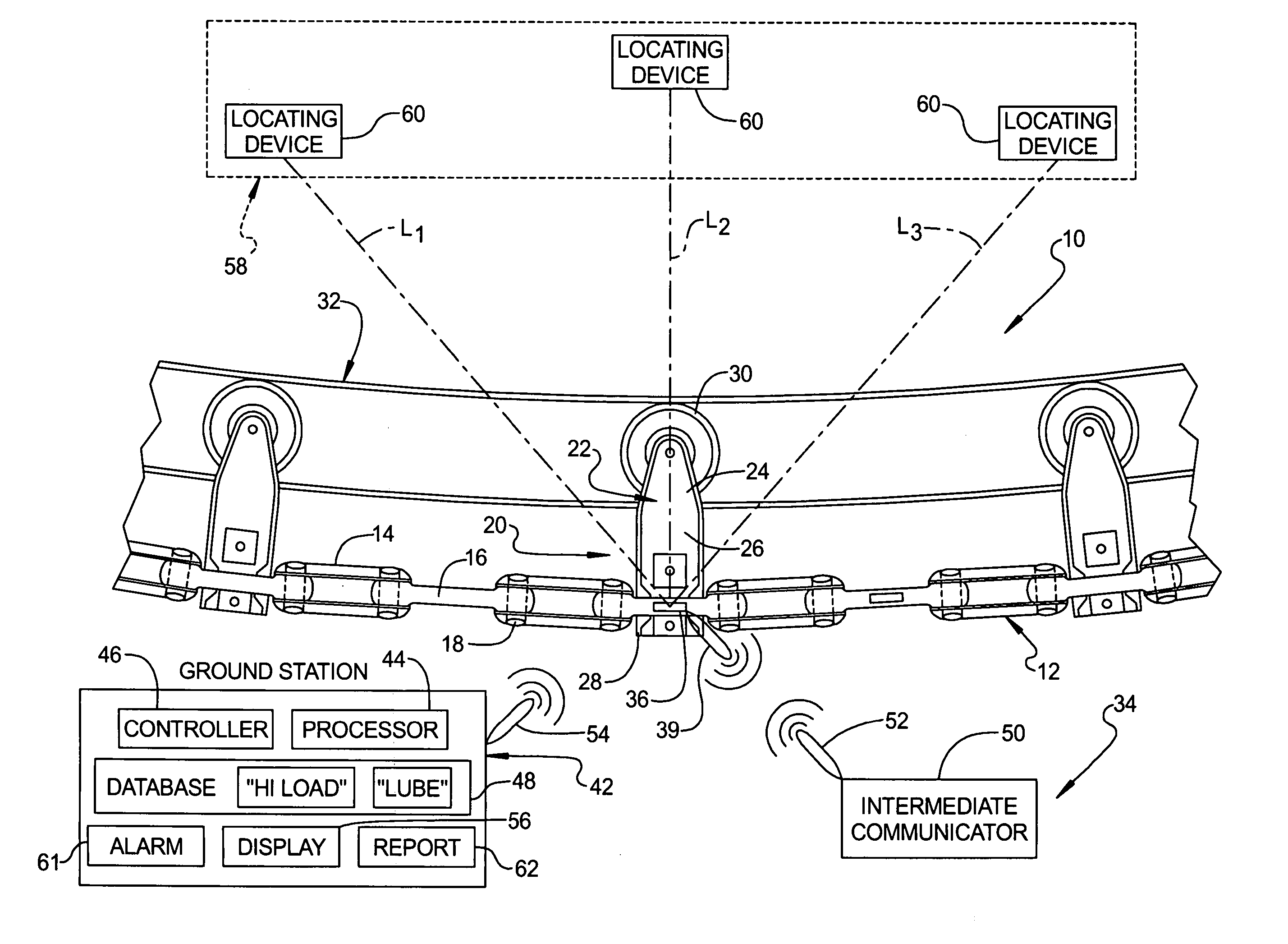
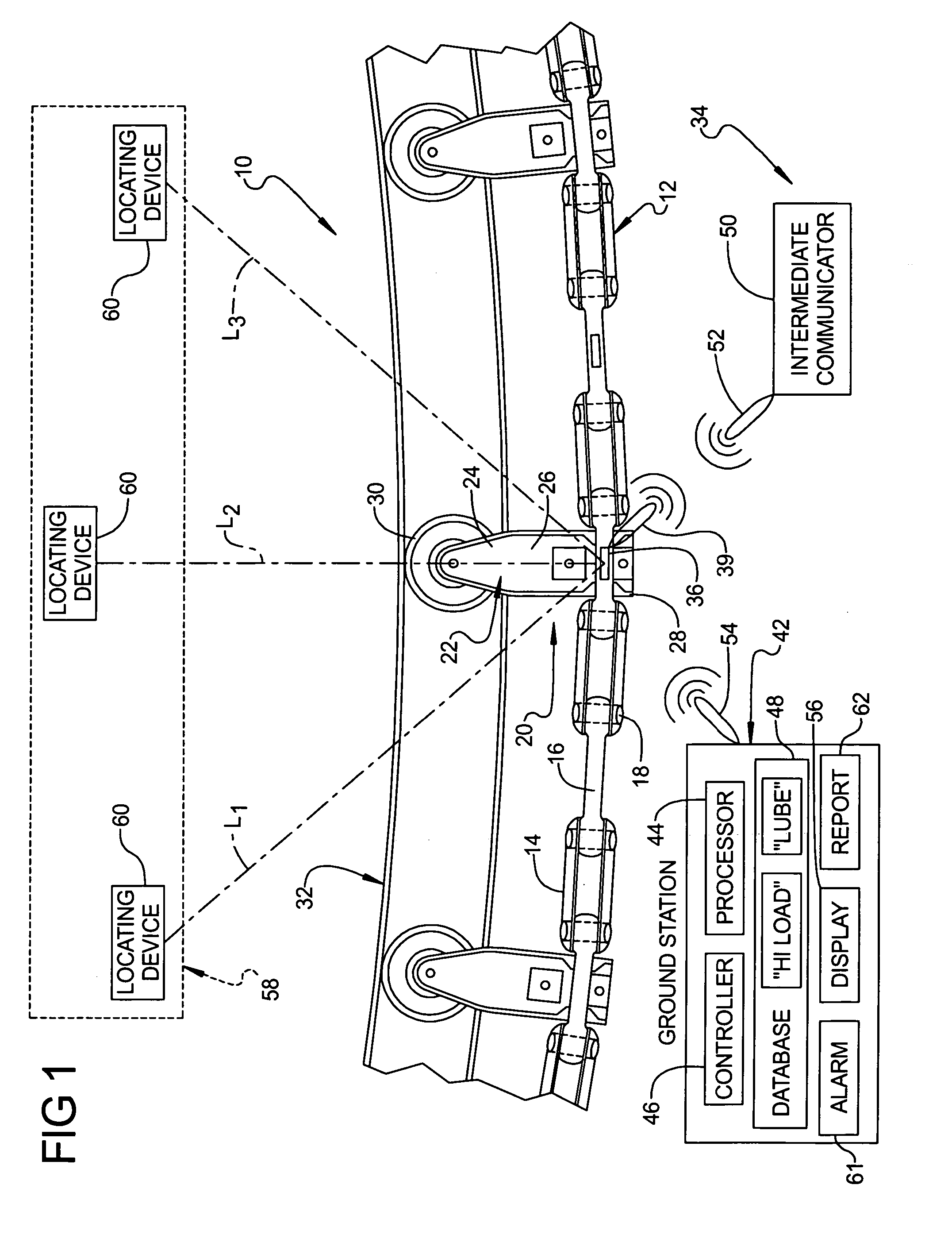
[0012] Referring to the drawings and in particular FIG. 1, one embodiment of a portion of a conveyor line assembly 10 is generally illustrated. As shown, the conveyor line assembly 10 includes a conveyor chain 12 having at least one—and preferably a plurality—of chain links. For instance, in the embodiment shown, the conveyor chain 12 includes a plurality of dual links 14 and a plurality of single links 16 coupled in alternating manner by pins 18. The conveyor line assembly 10 also includes a carrier assembly 20 for movably supporting the chain 12. The carrier assembly 20 includes trolleys 22 having an upper portion 24, an intermediate portion 26, and a lower portion 28. The upper portion 24 of each trolley 22 is pivotally coupled to a roller 30, and the roller 30 is rotationally supported by a beam 32. The intermed...


PUM


Abstract

A conveyor diagnostic system for monitoring loading of a conveyor line assembly including at least one sensor component coupled to the conveyor line assembly. The sensor component is adapted for detecting loading of the conveyor line assembly and is further adapted for generating and transmitting a signal that is correlative of the loading of the conveyor line assembly. The conveyor diagnostic system also includes a ground station adapted to receive and process the signal that is correlative of the loading of the conveyor line assembly. Furthermore, the conveyor diagnostic system includes a local positioning system that is adapted for detecting the location of the sensor component in relation to a reference point. A method of using the conveyor diagnostic system is also disclosed.

Description

FIELD OF THE INVENTION [0001] The present invention relates generally to a conveyor diagnostic system and, more specifically, to a conveyor diagnostic system having a local positioning system. BACKGROUND OF THE INVENTION [0002] Most conveyor line assemblies include moving parts, such as chains, rollers, and the like that undergo a significant amount of loading during operation. These loads may vary over time or may be concentrated in certain areas of the conveyor line assembly. For instance, loads on the conveyor line assembly can increase over the operating life of the assembly. Likewise, load concentrations can develop due to structural misalignment, wear, or lack of proper lubrication of certain components of the conveyor line assembly. Such loading can cause the conveyor line assembly to malfunction or fail, which can lead to losses in productivity. [0003] Conveyor diagnostic systems have been designed for measuring and monitoring these loads. Typical systems measure loading by ...

Claims


Application Information

Patent Timeline
Patent Type & Authority Applications(United States)
IPC IPC(8): B65G43/00
CPCB65G17/00B65G2203/0283B65G43/00
Inventor NASSAR, SAYEDGRZADZINSKI, GERRYGINDY, SHERIF
Owner FCA US
Why Eureka
Try Eureka