Fluid flow model and method of using the same

Inactive Publication Date: 2007-03-22
BAKER HUGHES INC
View PDF3 Cites 22 Cited by
  • Summary
  • Abstract
  • Description
  • Claims
  • Application Information

AI Technical Summary

Benefits of technology

[0008] The fluid flow model of the invention also allows for diversion effectiveness to

Problems solved by technology

Effective radial modeling is difficult to perform due to constraints imposed by the amount of core material typically available.
Since most reserv

Method used


Image

  • Fluid flow model and method of using the same
  • Fluid flow model and method of using the same
  • Fluid flow model and method of using the same

Examples


Example

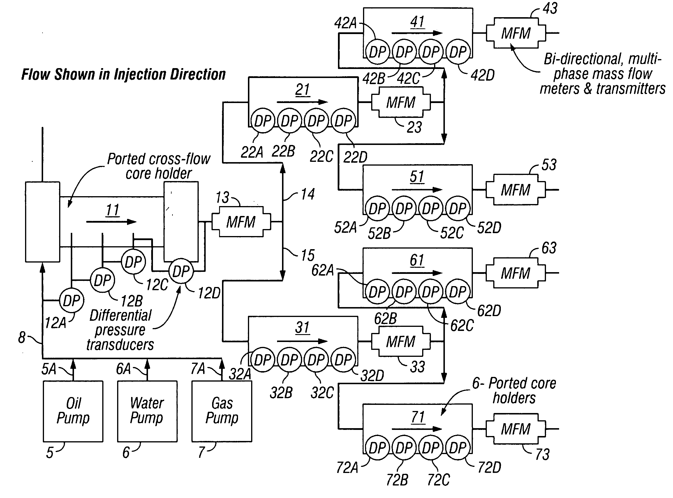
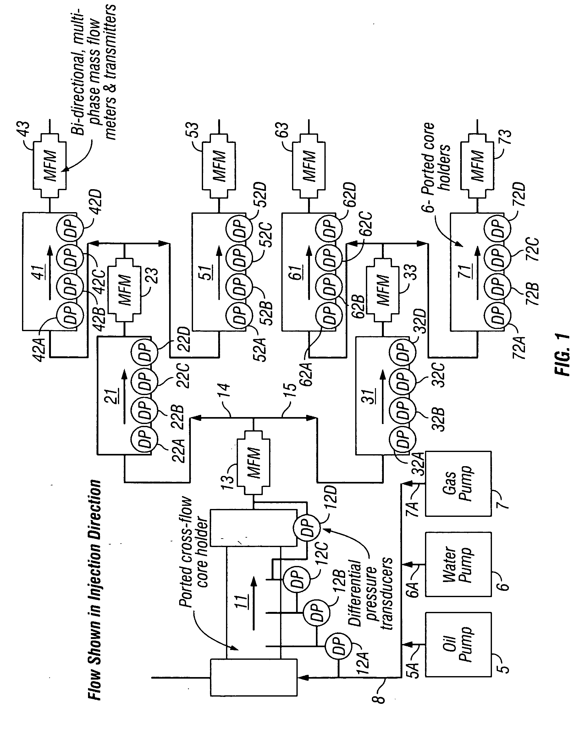
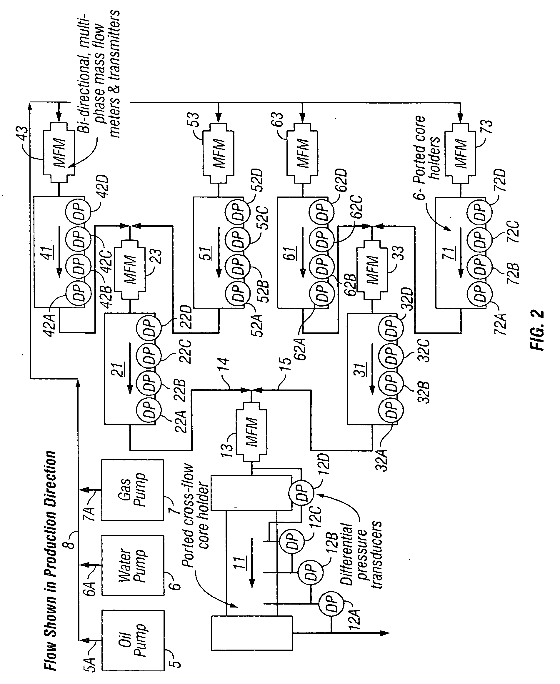
[0020] A design for reservoir modeling is disclosed which is more accurate than the methods of the prior art. In addition, the inventive modeling can be more readily scaled-up to the conditions in the field. The flow modeling test apparatus of the invention renders a more realistic depiction of the amount of treatment fluid needed by the operator, e.g., how much acid is needed to conduct an acidizing operation. The method has particular applicability in the estimation of treatment fluid for use in acidizing (including matrix acidizing and acid diversion) as well as water control treatment methods.

[0021] Typically, each of the referenced core holders discussed herein independently has an inner diameter of approximately 8 inches or less and a length of approximately 12 inches or greater. Typically, each of the cores has a diameter from about 1 to about 8 inches. (As used herein, the term “diameter” in relation to the core is synonymous with the outer diameter of the core.) Cores and ...


PUM


Abstract

A fluid flow model is comprised of one cross-flow style core holder and a multitude of standard style core holders, all connected by a concurrent combination of serial and parallel flow paths. The sum of these flow paths yields a fluid flow model that closely approximates a small radial slice of a conventional reservoir. The fluid flow model has particular applicability to estimate the requisite treatment fluid for use in acidizing as well as water control methods.

Description

[0001] This application claims the benefit of U.S. patent application Ser. No. 60 / 717,671, filed on September 16, 2005, herein incorporated by reference.FIELD OF THE INVENTION [0002] The present invention relates to a method and apparatus for determining certain fluid flow parameters for any porous media. BACKGROUND OF THE INVENTION [0003] Acidizing a hydrocarbon formation is the process of reacting an acid in the formation to enhance the flow of hydrocarbons to the wellbore. This can be through the dissolution of existing formation material or through the removal or bypass of blockage, often referred to as “damage to the well” which can be caused by natural or man-made conditions. Acidizing, or acid stimulation, opens up the channels around the wellbore, thereby improving the flow rate. When acid is injected into a formation, permeability is increased, thus enhancing the flow of hydrocarbons to the wellbore. This results in an increase or improvement in production from the formatio...

Claims


Application Information

Patent Timeline
IPC IPC(8): G01N15/08E21B47/10
CPCG09B7/02
Inventor KALFAYAN, LEONARD J.WOOD, WILLIAM D.CUTLER, JENNIFERDEVINE, CAROLYN S.
Owner BAKER HUGHES INC
Why Eureka
Try Eureka