
Load supporting apparatus with integrated coupling for lifting

a technology of load support and coupling, which is applied in the direction of lifting devices, lifting equipment, load-engaging elements, etc., can solve the problems of affecting the operation of the load support apparatus. , to achieve the effect of reducing the amount of time and effort, and quickly and easily removing

Inactive Publication Date: 2007-03-29
SEGURA VICTOR JOSEPH
View PDF6 Cites 3 Cited by
  • Summary
  • Abstract
  • Description
  • Claims
  • Application Information

AI Technical Summary

Benefits of technology

[0016] In certain applications, it may be desirable to allow a set of slings, attached to a piece of equipment or other load using the integrated lifting apparatus of the present invention in the manner set forth above, to remain attached to said piece of equipment or other load. By doing so, a user needs only to attach the line from a crane or hoist directly to the central link of such slips in order to attach to and lift the load in question. This greatly reduces the amount of time and effort required to attach individual sling lines to a load to be lifted, as well as the time and effort required to unhook same. Further, when a particular set of slings has been used for a predetermined number of lifts, such slings can be quickly and easily removed, replaced and discarded or refurbished, as desired.

Problems solved by technology

However, if such welds are required to support heavy loads on multiple lifts, over time such welds can become subject to fatigue and stress forces.
Obviously, when loads are being lifted over a large distance, such as from a boat to an offshore oil and gas platform, a broken weld on a pad-eye could have disastrous consequences.
A load dropped from a high elevation could severely damage property, or worse, injure or kill personnel in the area.

Method used


Image

  • Load supporting apparatus with integrated coupling for lifting
  • Load supporting apparatus with integrated coupling for lifting
  • Load supporting apparatus with integrated coupling for lifting

Examples


Embodiment Construction

)

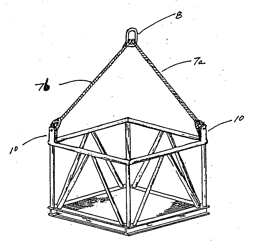
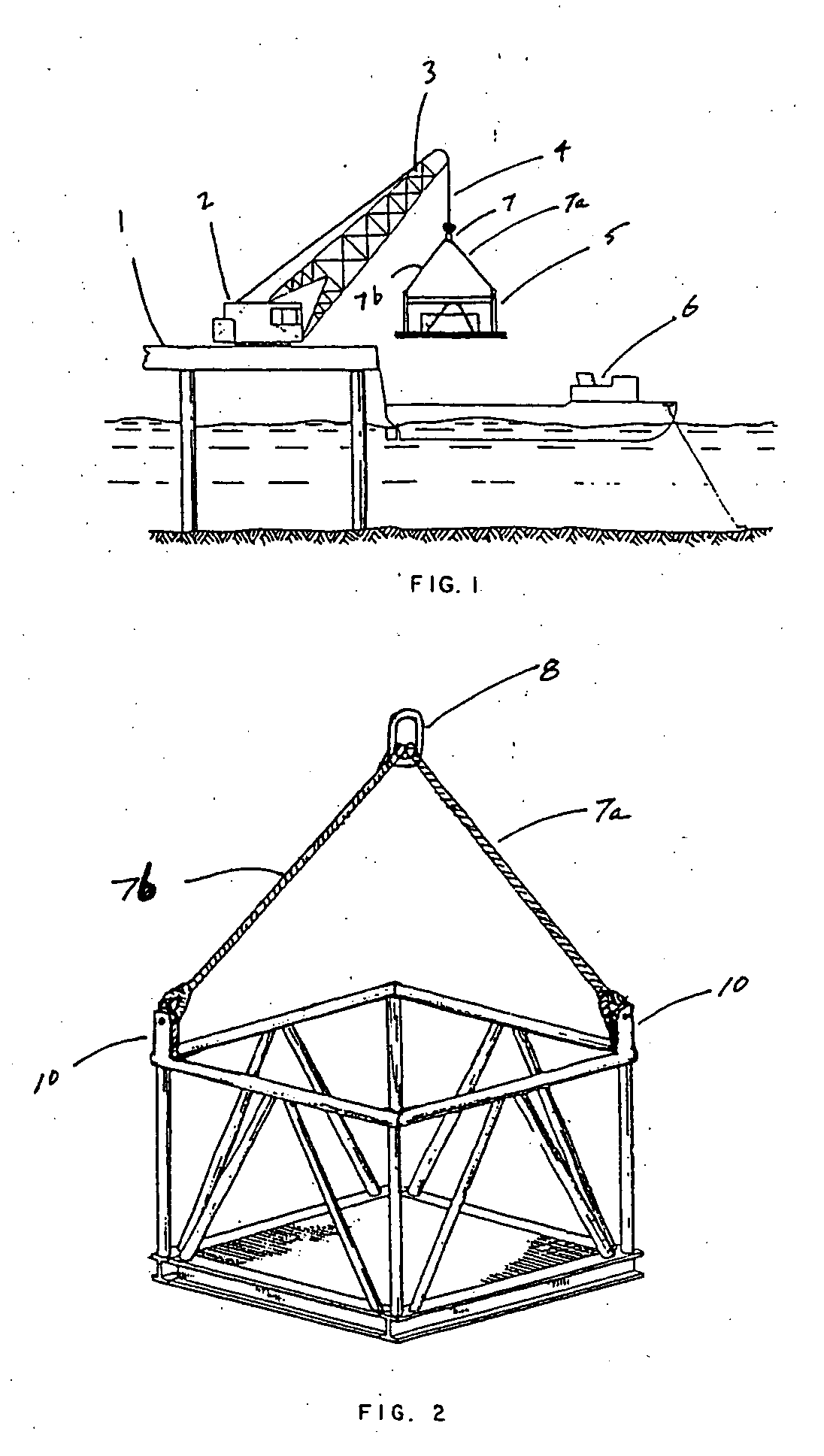
[0025] Referring to the drawings, FIG. 1 depicts a diagrammatic view of a piece of equipment, in this case a cargo basket, being loaded from an offshore platform to a waiting boat, using a crane. Platform 1 provides a foundation for crane 2, having boom 3 and line 4. Basket 5 is shown being lowered onto waiting boat 6 using crane 2. Slings 7 are used to connect line 4 of crane 2 to basket 5. Slings 7 utilize multiple lines 7a and 7b, to evenly distribute the weight of basket 5, and provide stability during the lift and transfer of basket 5 from platform 1 to boat 6.

[0026] It is well known in the prior art to utilize pad-eyes, welded or otherwise attached to a load such as basket 5, in order to provide connection means for attaching lines 7a and 7b of sling 7 to basket 5. The integrated lifting means of the present invention eliminates the need for such pad-eyes, and the numerous problems and safety concerns associated with such pad-eyes and / or similar devices.

[0027]FIG. 2 depicts...


PUM


Abstract

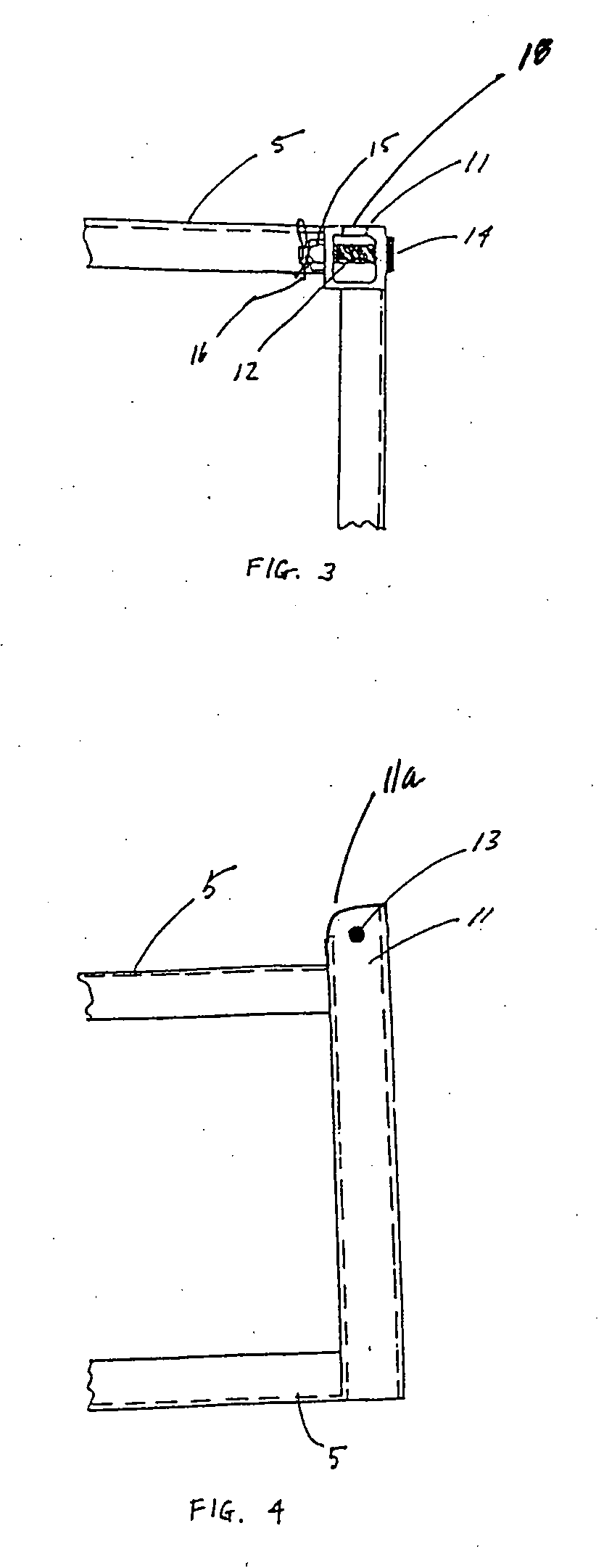
An integrated lifting apparatus for attaching to a sling has a generally horizontal base and at least one upright post extending from the base. Each post is generally hollow and has a cut-away upper surface, as well as a vertical slot near such upper surface. A horizontal bore extends through each post near its upper end. A threaded bolt having an enlarged head on one end, preferably constructed of high strength and / or shear resistant material, is inserted through each bore and the loop of a sling. A lock nut is threaded onto the end of the bolt to secure the bolt in place.

Description

CROSS REFERENCES TO RELATED APPLICATIONS [0001] This is a continuation of application Ser. No. 10 / 388,781 filed Mar. 14, 2003, currently pending, which is a continuation-in-part of application Ser. No. 09 / 814,553, filed Mar. 22, 2001, now abandoned.STATEMENTS AS TO RIGHTS TO INVENTIONS MADE UNDER FEDERALLY SPONSORED RESEARCH AND DEVELOPMENT [0002] None BACKGROUND OF THE INVENTION [0003] 1. Field of the Invention [0004] The present invention relates to a lifting apparatus which can be used in connection with a crane or hoist for the loading or unloading of cargo. More specifically, the present invention relates to a lifting apparatus which improves the strength characteristics of pallets, baskets and other structures used for containing or supporting loads being lifted, while eliminating the need for welded pad-eyes, loops or similar devices on such pallets, baskets or other structures. [0005] 2. Description of the Related Art [0006] Numerous devices have been devised for the purpose...

Claims


Application Information

Patent Timeline
Patent Type & Authority Applications(United States)
IPC IPC(8): A47J45/00B66C1/16
CPCB66C1/16B66C1/10
Inventor SEGURA, VICTOR JOSEPH
Owner SEGURA VICTOR JOSEPH
Learn More