Print head check method and image forming apparatus

Inactive Publication Date: 2007-04-05
SEIKO EPSON CORP
View PDF4 Cites 16 Cited by
  • Summary
  • Abstract
  • Description
  • Claims
  • Application Information

AI Technical Summary

Benefits of technology

[0006] The present invention has been made in the light of such a problem, and aims to provide a print head check method and an image forming apparatus that, by efficient implementation, shorten the time required for a ejection check of a print recording liquid, and for the entire processes of image forming.
[0008] According to this print head check method, an ejection check is performed in parallel with or in a partially overlapping manner with a predetermined image forming-related process that is required for printing, in order to confirm whether or not each of a plurality of nozzles of the print head actually ejects a print recording liquid. Accordingly, efficient implementation of the method can result in a reduction of the time required for a ejection check of the print recording liquid, and of time required for the entire range of processes.
[0014] According to this image forming apparatus, an ejection check is performed in parallel with or in a partially overlapping manner with a predetermined image forming-related process that is required for printing, in order to confirm whether or not each of a plurality of nozzles of the print head actually ejects a print recording liquid. Accordingly, efficient implementation of the method can result in a reduction of the time required for a ejection check of the print recording liquid, and of time required for the entire range of processes.

Problems solved by technology

However, the above described conventional printer did not take into consideration specific timings of implementing ink ejection checks.
Thus, for instance, the following problem can occur: a series of print processes such as feeding a recording sheet, printing on a recording sheet that has been fed, and ejecting the printed recording sheet, may well start only after an ink ejection check has taken place.
Thus, once they have started, it has taken an unduly long time for such processes to be completed.

Method used


Image

  • Print head check method and image forming apparatus
  • Print head check method and image forming apparatus
  • Print head check method and image forming apparatus

Examples


Embodiment Construction

[0033] In the following, the best embodiment for carrying out the present invention is described with reference to the drawings.

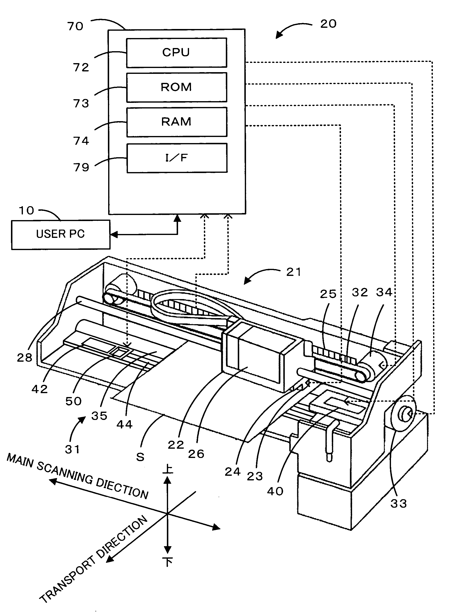
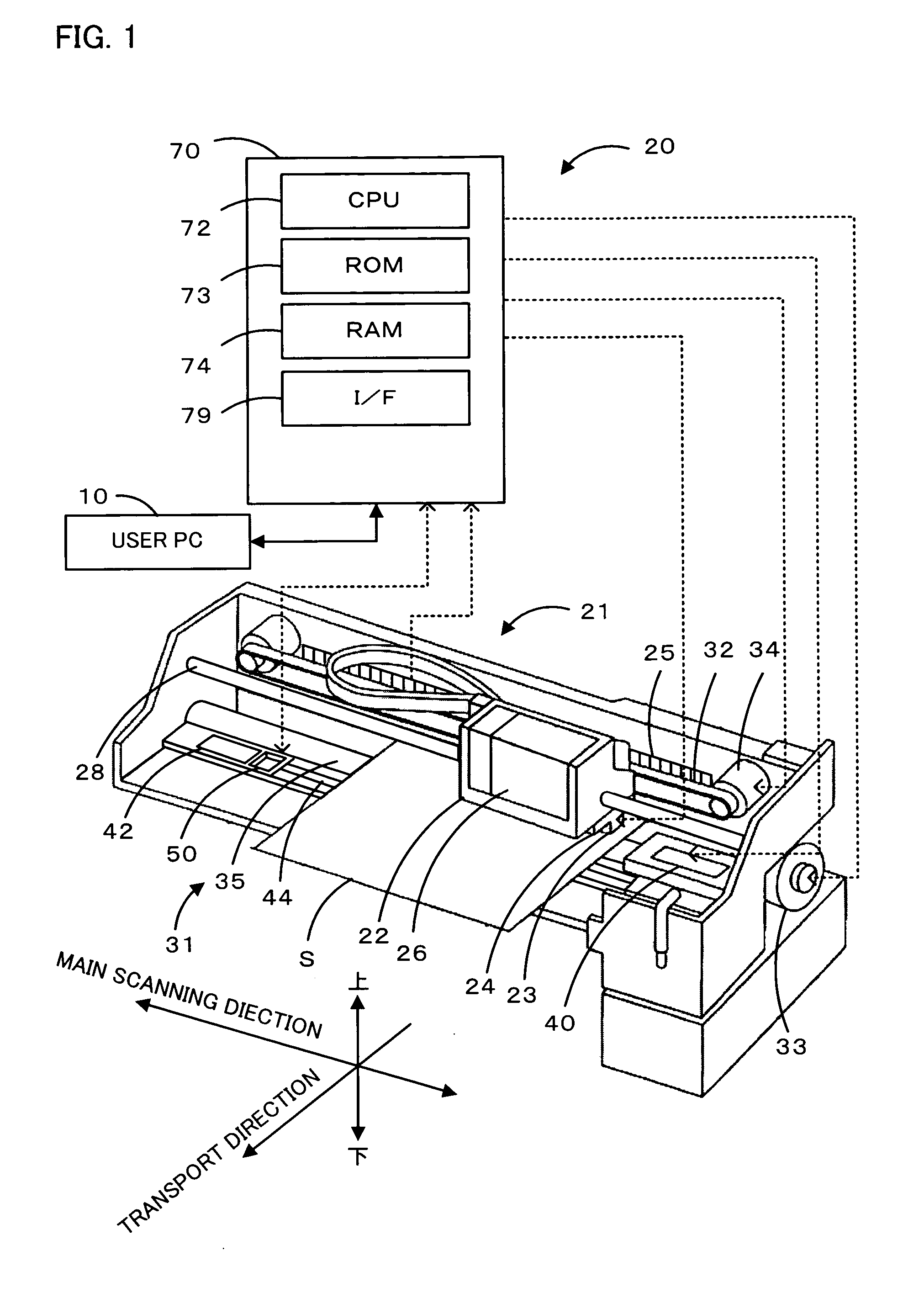
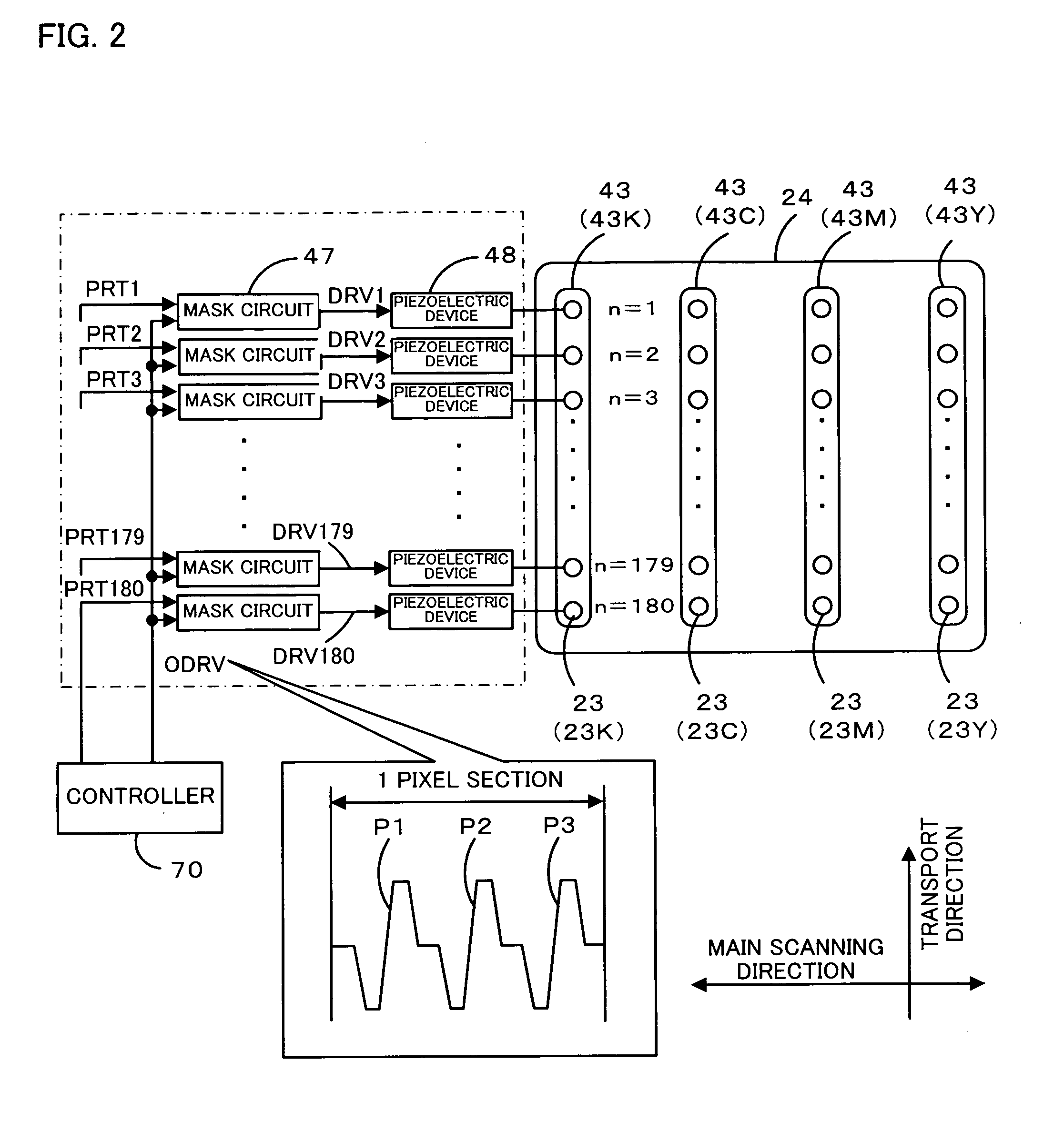
[0034]FIG. 1 is a block diagram schematically showing a configuration of an ink jet printer 20 including a print head check unit 50, which is one embodiment of the invention. FIG. 2 is an illustration of the print head 24. FIG. 3 is an illustration of the paper handling mechanism 31. FIG. 4 is a block diagram schematically showing a configuration of a print head check unit 50.

[0035] As shown in FIG. 1, the ink jet printer 20 of this embodiment includes a printer mechanism 21 having an ink head 24 or a carriage 22, etc., a paper handling mechanism 31 including a line feed roller 53 driven by a drive motor 33, a cap unit 40 formed in the vicinity of the right edge of a platen 44, a print head check unit 50 formed adjacent to a flashing area 42 on the platen 44 for the purpose of checking whether or not the print head ejects ink droplets normally, and a cont...


PUM


Abstract

A printer has a print head check unit that performs an ink ejection check to confirm whether or not ink is being ejected normally from nozzles, based on induced voltage generated when charged ink droplets are ejected onto a check area. Upon receipt of a print instruction (S100), the printer sets a flag F to 1 so as to start an ink ejection check and starts a paper feed process (S110). When the processes has been terminated (S120, S130), the printer starts printing. Accordingly, as an ink ejection check takes place concurrently with the paper feed process, the overall time required for the processes can be reduced, in comparison with any method in which the processes are executed separately. In this way, because of efficient implementation, the overall time required for the processes of the ejection check of the print recording liquid and an image forming process can be reduced. In addition, the ink ejection check may be performed in parallel with or partly overlapping with a process of receiving print data, a process of conversion into print data, a process of ejecting paper after printing, or a flashing process, etc.

Description

BACKGROUND OF THE INVENTION [0001] 1. Field of the Invention [0002] The present invention relates to a print head check method and an image forming apparatus. [0003] 2. Description of the Related Art [0004] A conventionally proposed printer has an inspection unit that includes a light emitting unit, as well as a light receiving unit at a position through which ink droplets ejected from nozzles of a print head pass, an inspection unit that checks ink droplets ejected from the nozzles. (For example, refer to Japanese Patent Application Laid-Open No. 2005-35309.) In this proposed printer, the light receiving unit sense whether or not light emitted from the light emitting unit is shielded by ink droplets ejected from the nozzles of the print head, in order to check whether or not ink droplets have been ejected from the nozzles. When a nozzle is clogged, a cleaning process is executed so that printing can start with no nozzle clogged, thereby ensuring inhibition of degradation in picture...

Claims


Application Information

Patent Timeline
IPC IPC(8): B41J29/38
CPCB41J2/16579B41J29/393B41J2/165
Inventor IZUO, SEIJI
Owner SEIKO EPSON CORP
Why Eureka
Try Eureka