Display device for circular saw

a display device and circular saw technology, applied in the field of circular saws, can solve the problems of inability to clearly see, wear of marks b>92/b>, and dangerous actions, and achieve the effect of convenient checking and safer for users

Inactive Publication Date: 2007-04-12
REXON IND CORP LTD
View PDF32 Cites 10 Cited by
  • Summary
  • Abstract
  • Description
  • Claims
  • Application Information

AI Technical Summary

Benefits of technology

[0004] The present invention intends to provide a circular saw with a display device which is easy to check and safer for the user.

Problems solved by technology

However, the marks 83 are easily covered by debris during cutting and the user has to frequently wipe out the debris to see the marks 83, and this action is dangerous.
Nevertheless, the marks 92 would be worn out after a period of time of use and cannot be seen clearly.

Method used


Image

  • Display device for circular saw
  • Display device for circular saw
  • Display device for circular saw

Examples


Embodiment Construction

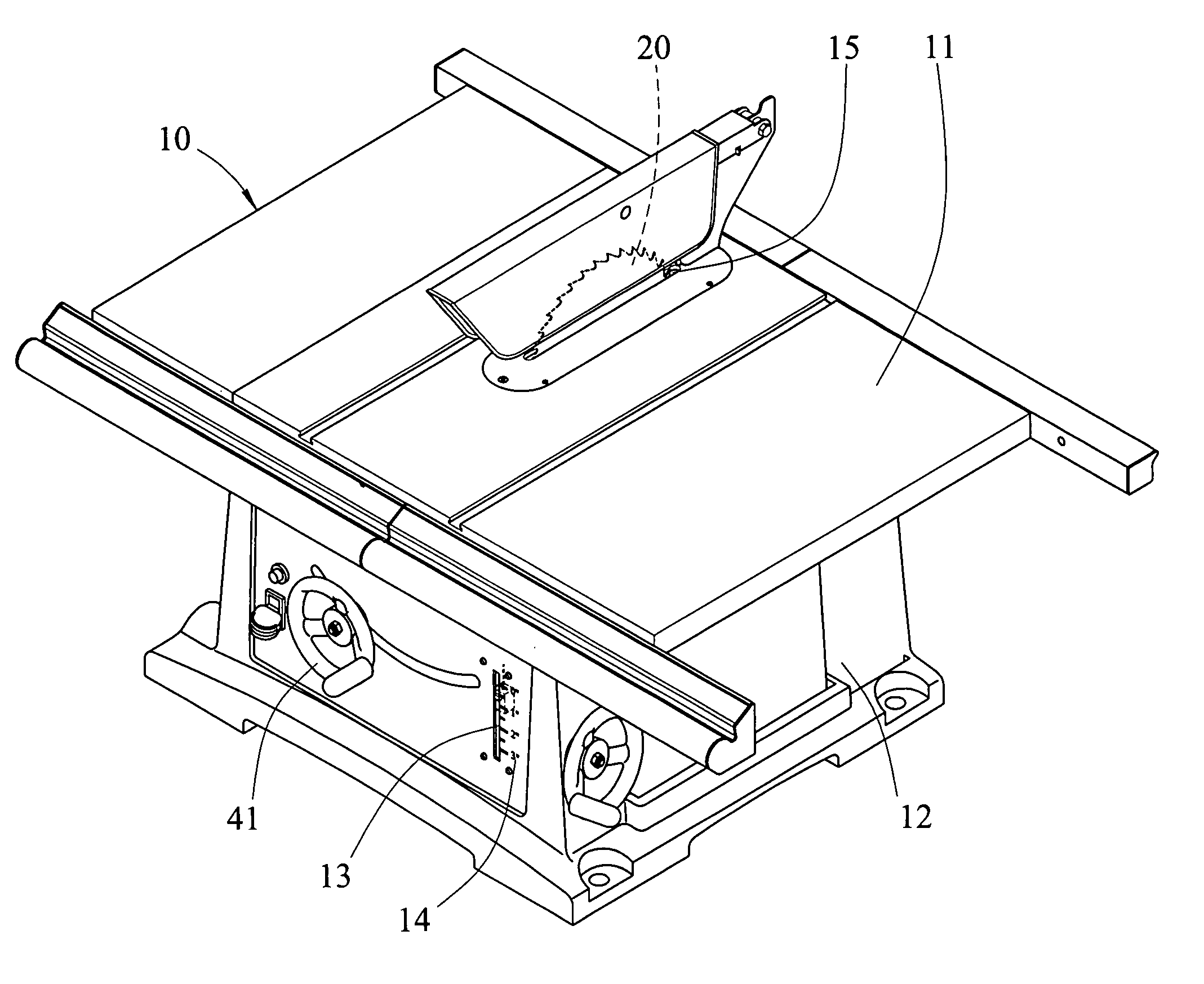
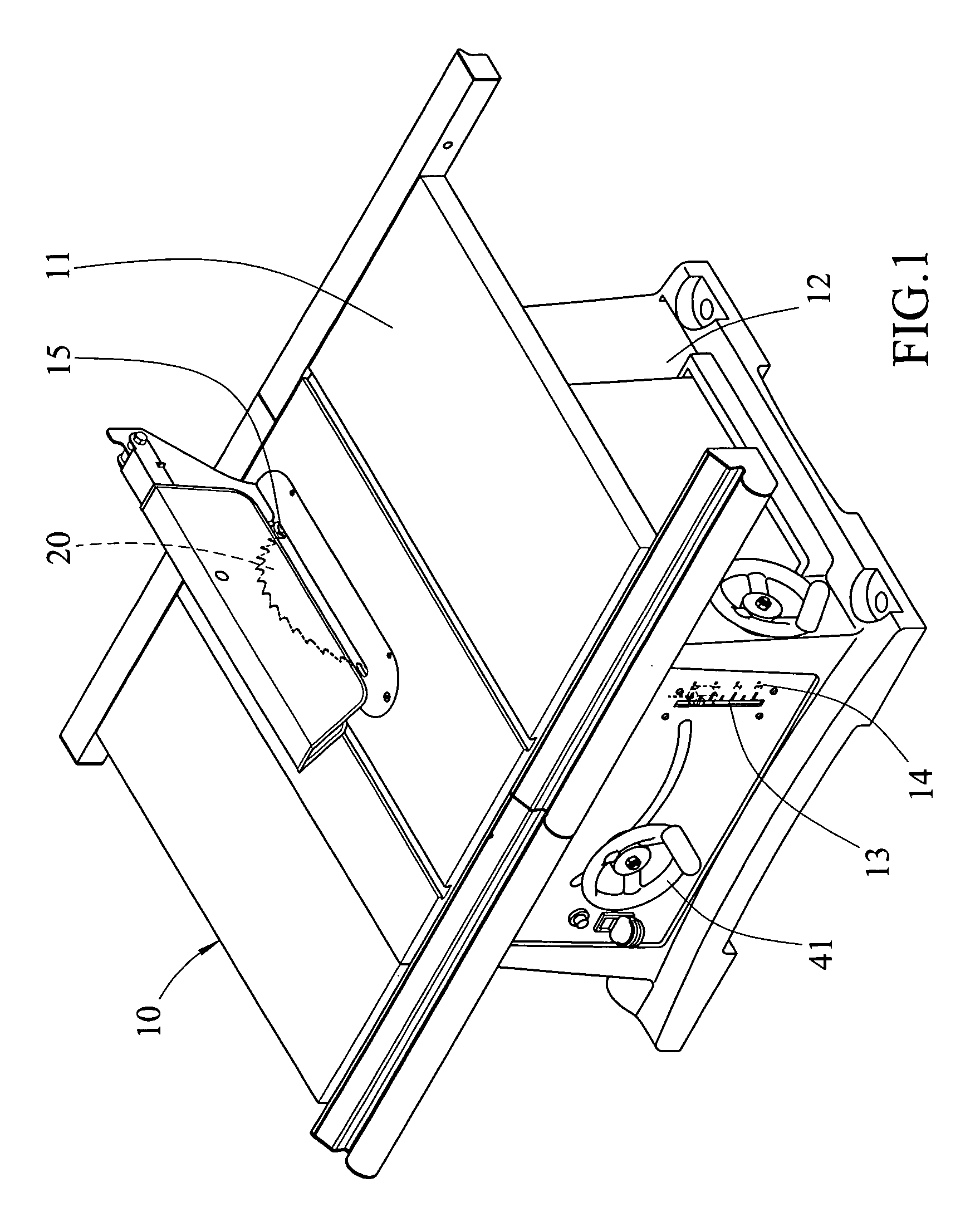
[0018] Referring to FIGS. 1 to 6, the circular saw 10 of the present invention, for example a table saw, comprises a base 12 with a table 11 supported on the base 12, a first slot 15 defined through the table 11 so that a blade 20 movably extends through the first slot 15. A blade unit 30 is pivotably located in the base 12 and connected with the blade 20 so as to control the blade 20. The blade unit 30 includes a threaded rod 32 and a bevel gear 31 is connected with the threaded rod 32. When the threaded rod 32 is rotated, the blade unit 30 is moved up and down. The blade unit 30 includes a motor 33 which is connected to and drives the blade 20.

[0019] An adjustment unit 40 is connected with the blade unit 30 for moving the blade unit 30 relative to the table 11 and includes a handwheel 41 which is located on outside of the base 12, and a rod 42. The rod 42 has one end connected to the handwheel 41 and the other end of the rod 42 is connected with the blade unit 30. Another bevel g...


PUM

PropertyMeasurementUnit
heightaaaaaaaaaa
timeaaaaaaaaaa
movementaaaaaaaaaa

Abstract

The present invention is a circular saw including a base, a blade movably extending through the first slot, a blade unit mounted to the base and connected with the blade, an adjustment unit connected with the blade unit for moving the blade unit relative to the base, an display device, and a connection member. The display device has a groove member fixed on the base, a spring member disposed into the groove member and an indication member disposed into the groove member. The spring member has an end connected to the groove member and the other end connected to the indication member. The connection member has one end connected to the blade unit and the other end connected to the indication member. The blade unit synchronously moves the blade and pulls the connection member to draw the indication member when the blade unit is moved.

Description

FIELD OF THE INVENTION [0001] The present invention relates to a circular saw, and more particularly the circular saw has a display device. BACKGROUND OF THE INVENTION [0002] A conventional table saw 80 is shown in FIG. 9 and generally includes a base 81 with a table 84 supported on the base 81, a slot 82 is defined through the table 84 so that the blade 85 extends through the slot 82 so as to cut objects on the table 84. A handwheel 86 is located on an outside of the base 81 and connected with the mechanism of the blade 85 such that when rotating the handwheel 86, the blade 85 is moved through the slot 82 vertically. Indication marks 83 are marked on the table 84 so that the user can check the specific mark 83 that meets the teeth of the blade 85 to acknowledged the height of the blade 85 above the table 84. However, the marks 83 are easily covered by debris during cutting and the user has to frequently wipe out the debris to see the marks 83, and this action is dangerous. [0003] A...

Claims


Application Information

Patent Timeline
Patent Type & Authority Applications(United States)
IPC IPC(8): B26D5/08
CPCB23D45/068B23D59/002Y10T83/8773
Inventor CHEN, JUNG-HUO
Owner REXON IND CORP LTD
Why Eureka
Try Eureka