
Method and system for implementing virtual router redundacy protocol on a resilient packet ring

a packet ring and virtual router technology, applied in the field of routing technologies, can solve the problems that the method of the prior art cannot meet this network requirement, and the slow speed of the master/backup switch cannot meet the requirements of some real-time services

Inactive Publication Date: 2007-04-12
HUAWEI TECH CO LTD
View PDF6 Cites 21 Cited by
  • Summary
  • Abstract
  • Description
  • Claims
  • Application Information

AI Technical Summary

Benefits of technology

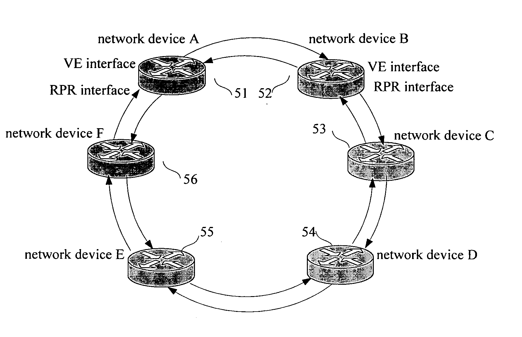
[0018] It can be seen from the above solution that, in accordance with the method of the present invention, which is for implementing VRRP on a Resilient Packet Ring, a Virtual Ethernet (VE) interface is set on the RPR for network devices which are about to constitute VRRP groups, and all the VE interfaces of the network devices constituting the VRRP groups and the RPR interfaces will be classified into a same virtual local area network (VLAN). Then, the VRRP will be run in the classified VLAN, so as to implement the VRRP on the RPR. In addition, because the VE interface set in the network device can support multiple MAC addresses, a plurality of VRRP groups can be generated on the RPR simultaneously according to this method, so that the RPR may possess a plurality of virtual layer 3 switch devices.
[0019] Furthermore, the present invention provides a system for implementing VRRP on an RPR, where the RPR interfaces of network devices in the system are configured to support the bridge mode, and the VE interfaces are set in the network devices constituting VRRP groups. Then, the VRRP will be run at the VE interfaces, so that a plurality of VRRP groups can be generated on the RPR.

Problems solved by technology

Consequently, when there is a need to generate a plurality of virtual layer 3 switch devices by running the VRRP in order to provide multifunctional services and larger transmission bandwidth, the method of the prior art is unable to meet this network requirement.
The slow speed of master / backup switch can not satisfy the requirements of some real-time services.

Method used


Image

  • Method and system for implementing virtual router redundacy protocol on a resilient packet ring
  • Method and system for implementing virtual router redundacy protocol on a resilient packet ring
  • Method and system for implementing virtual router redundacy protocol on a resilient packet ring

Examples


Embodiment Construction

[0025] In a preferred embodiment of the present invention, an interface that can support a plurality of MAC addresses is set on an RPR interface of a network device on an RPR, and the interface supporting a plurality of MAC addresses and the RPR interface are classified into a same VLAN, and then a VRRP is run in the classified VLAN, so as to implement a plurality of virtual layer 3 switch devices on the RPR.

[0026] In this embodiment, the interface which can support a plurality of multiple MAC addresses is a VE interface. Since the VE interface is required to be set on the RPR interface of the network device on the RPR, the RPR interface of the network is required to support the bridge mode. The specific reason is as follows: all messages transmitted from the VE interface are layer 2 Ethernet messages, and if the RPR interface is in the routing mode, these messages can not be born on the RPR directly; while network devices in the bridge mode can encapsulate layer 2 Ethernet message...


PUM


Abstract

A method for implementing Virtual Router Redundancy Protocol (VRRP) on a Resilient Packet Ring (RPR), including: setting an interface supporting a plurality of Medium Access Control (MAC) addresses for each RPR interface of network devices to constitute VRRP groups; classifying the RPR interfaces of network devices to constitute VRRP groups, and the interfaces supporting a plurality of MAC addresses, into one virtual local area network (VLAN); running the VRRP in the classified VLAN to generate at least one virtual layer 3 switch device. Also, the present invention discloses a system for implementing VRRP on an RPR. In the method and system of the present invention, a plurality of virtual layer 3 switch devices are generated by means of setting a VE interface in the network device and running the VRRP in the VLAN which contains both the VE interface and the RPR interface.

Description

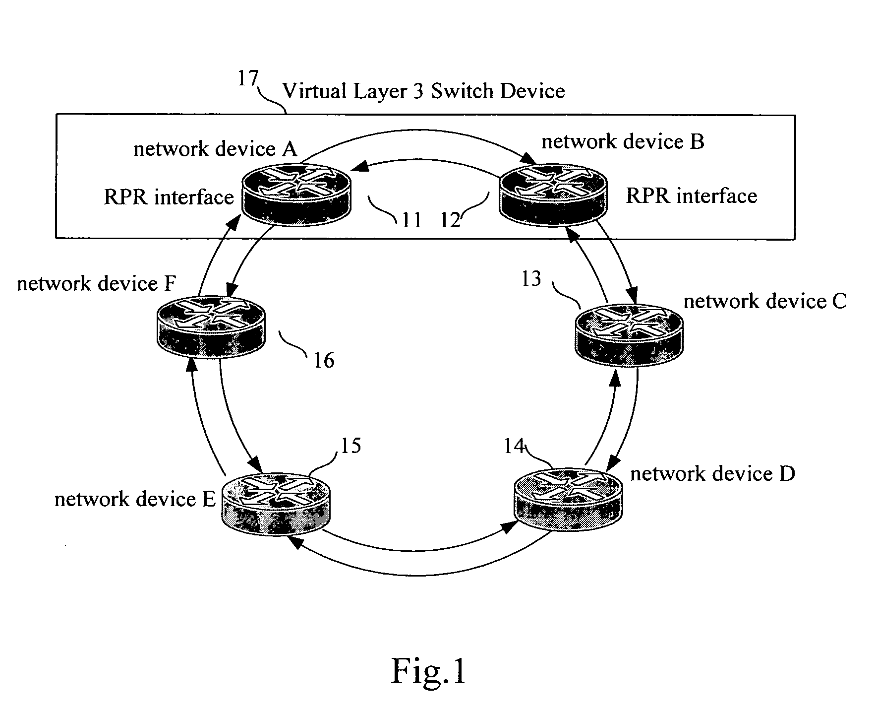
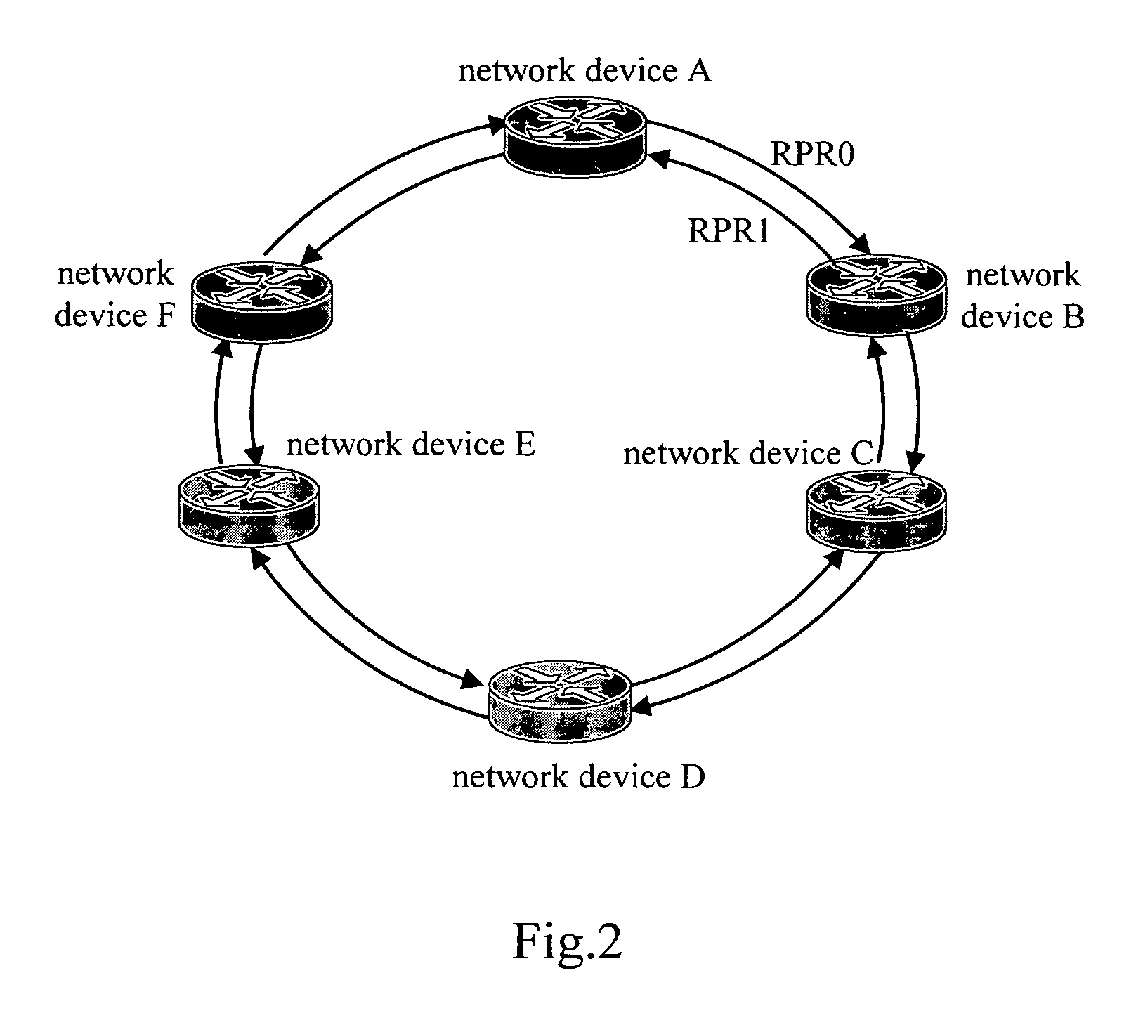
[0001] This application claims priority to Chinese Patent Application No. 200510106585.6, filed Oct. 8, 2005, which is hereby incorporated by reference. [0002] 1. Field of the Invention [0003] The present invention relates to routing technologies, and particularly, to a method and system for implementing Virtual Router Redundancy Protocol (VRRP) on a Resilient Packet Ring. [0004] 2. Background of the Invention [0005]FIG. 1 illustrates the architecture of a system for implementing a Virtual Router Redundancy Protocol (VRRP) on a Resilient Packet Ring (RPR) in the prior art. As shown in FIG. 1, the RPR includes a network device A11, a network device B12, a network device C13, a network device D14, a network device E15 and a network device F16. The network devices from A11 to F16 can support the RPR protocol, and an RPR interface of each network device may support two work modes, namely a routing mode and a bridge mode respectively. The routing mode means to bear an IP service or an MP...

Claims


Application Information

Patent Timeline
Patent Type & Authority Applications(United States)
IPC IPC(8): H04L12/56H04L12/54
CPCH04L12/433H04L12/437H04L12/56H04L29/10H04L45/586H04L69/32H04L69/325
Inventor LI, JIAN
Owner HUAWEI TECH CO LTD
Learn More