Loudspeaker with field replaceable parts and method of assembly

a technology of loudspeaker and replaceable parts, applied in the field of loudspeakers, to achieve the effect of facilitating assembly and repair of the speaker, and minimizing the stacking of concentration tolerances

Active Publication Date: 2007-04-19
JL AUDIO
View PDF5 Cites 1 Cited by
  • Summary
  • Abstract
  • Description
  • Claims
  • Application Information

AI Technical Summary

Benefits of technology

[0010] The loudspeaker and method of assembly of this invention provides for precise alignment between the frame and motor structure before they are connected to one another, and employs a fixture to form the moving assembly of the speaker, i.e. the voice coil, upper and lower suspensions and diaphragm, outside of the frame so that concentric tolerance stack-up is minimized. The moving assembly, once formed, is mounted as a unit to the frame and motor structure to facilitate assembly and repair of the speaker.
[0012] In the event of a failure of one of the elements of the moving assembly, which is typically where a problem arises, the entire moving assembly is disconnected from the frame and motor structure and removed. A new moving assembly, fabricated at the factory and shipped as a unit to a retailer or off-site repair center, is then mounted to the frame and motor structure in the field. As noted above, and described below, aligning pins on elements of the moving assembly and bores formed in the frame and motor structure allow for precise alignment of all speaker elements when the moving assembly is replaced without using gauges, guides, fixtures or other special equipment. Additionally, no dust cap is required with the speaker of this invention because the diaphragm may be formed without a central opening.
[0013] In addition to the simplification of repairs, the loudspeaker herein and its method of assembly substantially eliminates deformation of the upper suspension even at high voice coil excursions. A centering fixture is employed to precisely align the frame and motor structure before they are secured together. An assembly fixture is used to form the moving assembly which, together with elements of the moving assembly, is machined to precise tolerances to ensure concentric alignment and centering of the voice coil, the upper and lower suspensions and the diaphragm relative to one another as they are interconnected on the assembly fixture. Additional features of this invention further reduce tolerance stack-up among the parts of the moving assembly. As a result, little or no deformation of the upper suspension is required for the voice coil to axially move in concentric relation to the pole piece within the magnetic gap during operation of the speaker.

Problems solved by technology

In the event of a failure of one of the elements of the moving assembly, which is typically where a problem arises, the entire moving assembly is disconnected from the frame and motor structure and removed.

Method used


Image

  • Loudspeaker with field replaceable parts and method of assembly
  • Loudspeaker with field replaceable parts and method of assembly
  • Loudspeaker with field replaceable parts and method of assembly

Examples


Embodiment Construction

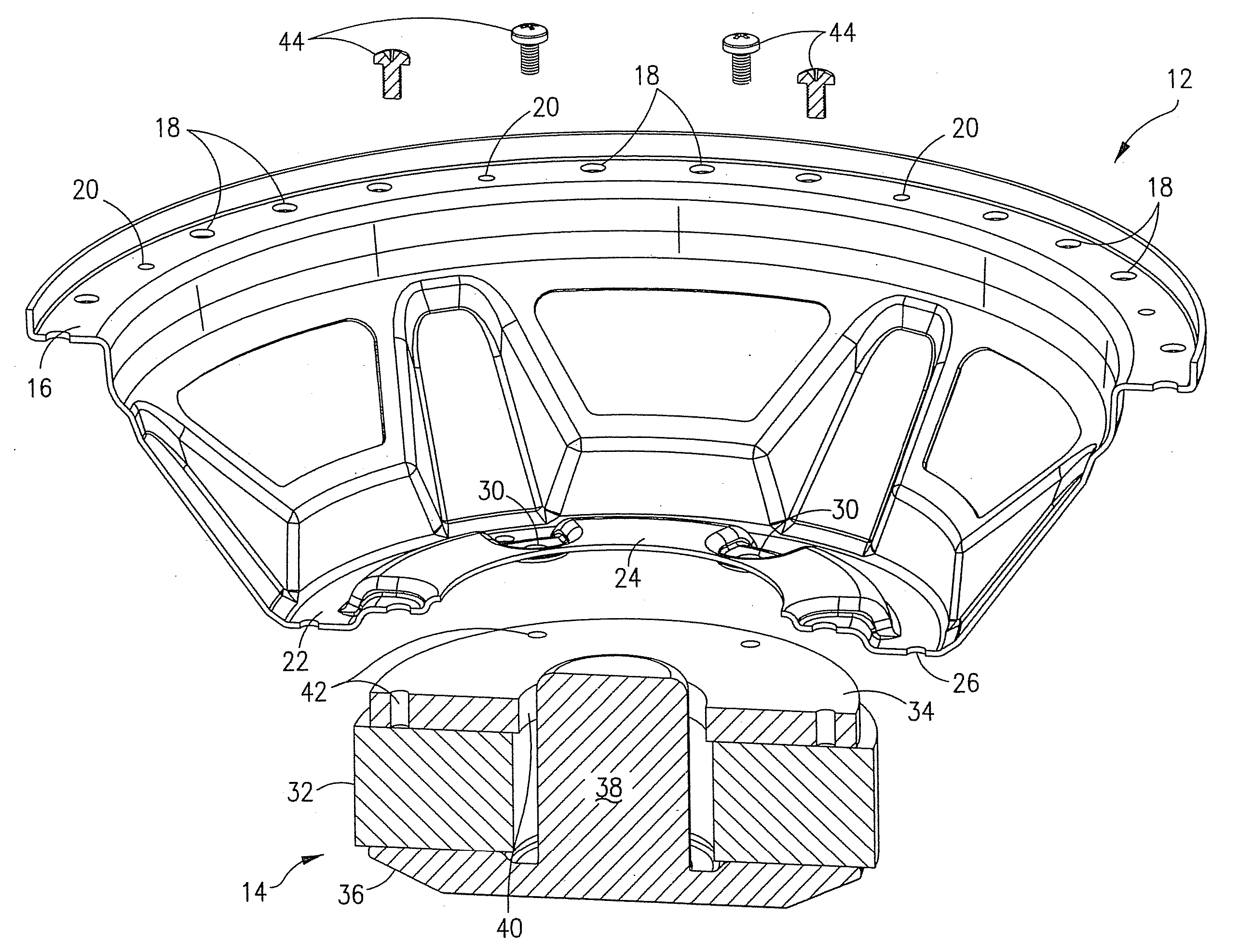
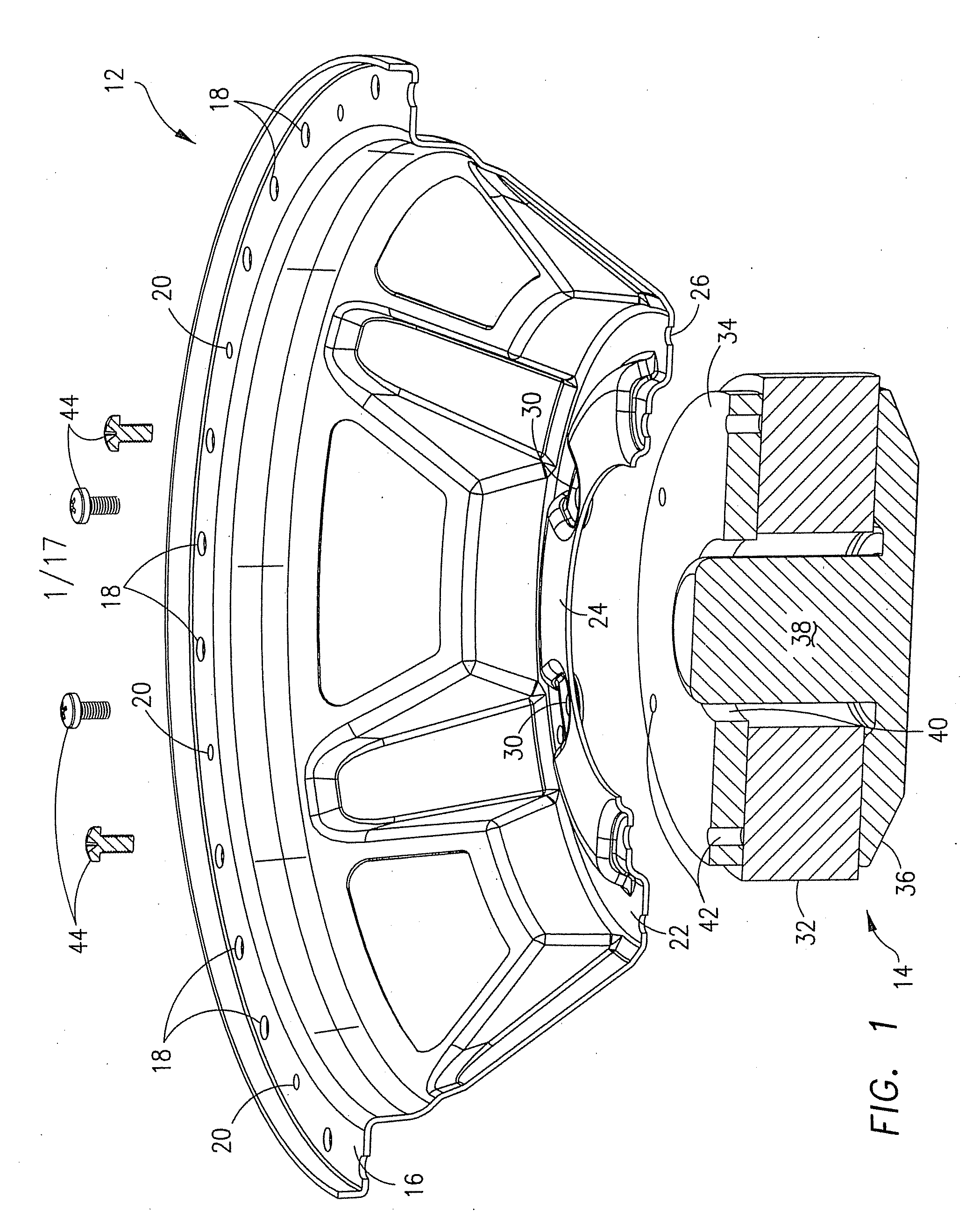
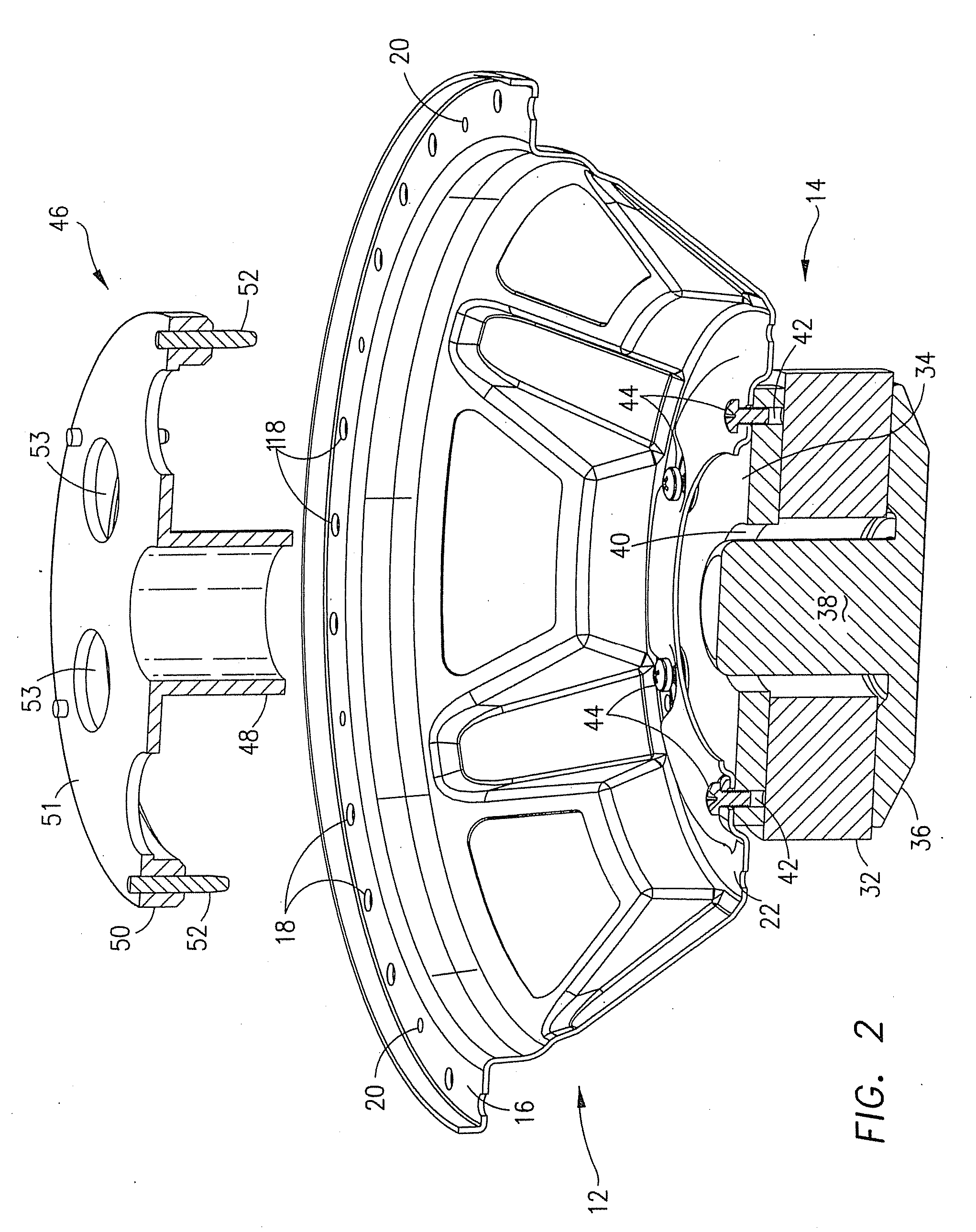
[0032] Referring now to the drawings, a loudspeaker 10 is illustrated by a series of assembly steps beginning with FIG. 1 and ending with the completed speaker 10 shown in FIG. 15. The structure of speaker 10 will be discussed in the course of describing its assembly, with sequential reference to the Figs. Throughout the following description, the terms “top,”“bottom,”“upper” and “lower” are meant to refer to directions and / or locations with the speaker 10 in the orientation shown in the Figs. The terms “inner” and “outer” refer to a radial relationship of parts or structure beginning at the longitudinal axis of the speaker 10 which, for purposes of this discussion, is considered to pass throughout the pole piece 38, described below.

Assembly of Frame and Motor Structure

[0033] With reference initially to FIGS. 1-3 and 15, the speaker 10 has a frame 12 and a motor structure 14. The frame 12 has an upper flange 16 formed with a number of spaced, surround locator holes 18 and a numbe...


PUM

PropertyMeasurementUnit
magneticaaaaaaaaaa
magnetic gapaaaaaaaaaa
electrical energyaaaaaaaaaa

Abstract

A loudspeaker and method of assembly according to this invention provides for precise alignment between the frame and motor structure before they are connected to one another, and employs a fixture to form the moving assembly of the speaker, i.e. the voice coil, upper and lower suspensions and diaphragm, outside of the frame so that concentric tolerance stack-up is minimized. The moving assembly, once formed, is mounted as a unit to the frame and motor structure to facilitate assembly and repair of the speaker.

Description

FIELD OF THE INVENTION [0001] This invention relates to loudspeakers, and, more particularly, to a loudspeaker having field replaceable parts and a method of assembling the loudspeaker. BACKGROUND OF THE INVENTION [0002] Loudspeakers generally comprise a frame, a motor structure, a diaphragm, a lower suspension or spider and a surround or upper suspension. In one type of speaker, the motor structure includes a permanent magnet sandwiched between a top plate and a back plate, with a pole piece centrally mounted on the back plate so that both the top plate and magnet are concentrically disposed about the pole piece. A magnetic gap is formed between the pole piece and top plate within which a voice coil is axially movable. Preferably, the voice coil consists of a hollow, cylindrical-shaped former having an inner surface and an outer surface which mounts a winding of wire. [0003] The voice coil in speakers of the type described above is mounted within the magnetic gap by the upper and l...

Claims


Application Information

Patent Timeline
Patent Type & Authority Applications(United States)
IPC IPC(8): H04R9/06H04R11/02H04R1/00H04R1/02H04R9/04H04R31/00
CPCH04R9/043H04R9/06H04R31/006Y10T156/1052Y10T156/108Y10T29/49002Y10T29/49005Y10T29/4902Y10T29/4908
Inventor PRONI, LUCIO
Owner JL AUDIO
Why Eureka
Try Eureka