Reinforced supporting connectors for tubular grab railings

a technology of supporting connectors and tubular grab railings, which is applied in the direction of rod connections, curtain suspension devices, handrails, etc., can solve the problems of reducing affecting the service life of tubing,

Active Publication Date: 2007-04-19
GOAD EUGINE W
View PDF41 Cites 29 Cited by
  • Summary
  • Abstract
  • Description
  • Claims
  • Application Information

AI Technical Summary

Problems solved by technology

Consequently, grab bar systems now in use are formed from metal such as stainless steel or aluminum in order to have the strength needed to meet code requirements and accordingly are relatively expensive and have decorative and aesthetic limitations.
While plastic grab bars have been previously proposed, e.g., formed from a plastic polymer as described, for example, in U.S. Pat. No. 5,690,237, it is difficult or impossible for plastic to meet the strength requirements set by building codes and they weaken with age.
In addition, the patented device is not suited for use with commercially available tubing.
Another problem is the difficulty associated with drilling holes and inserting grab bar mounting screws through a mounting flange often in a location that is beneath or behind the horizontally extending portions of the grab bar support unit.
This is time consuming, labor intensive, and often results in screws that are cocked to one side.

Method used


Image

  • Reinforced supporting connectors for tubular grab railings
  • Reinforced supporting connectors for tubular grab railings
  • Reinforced supporting connectors for tubular grab railings

Examples


Embodiment Construction

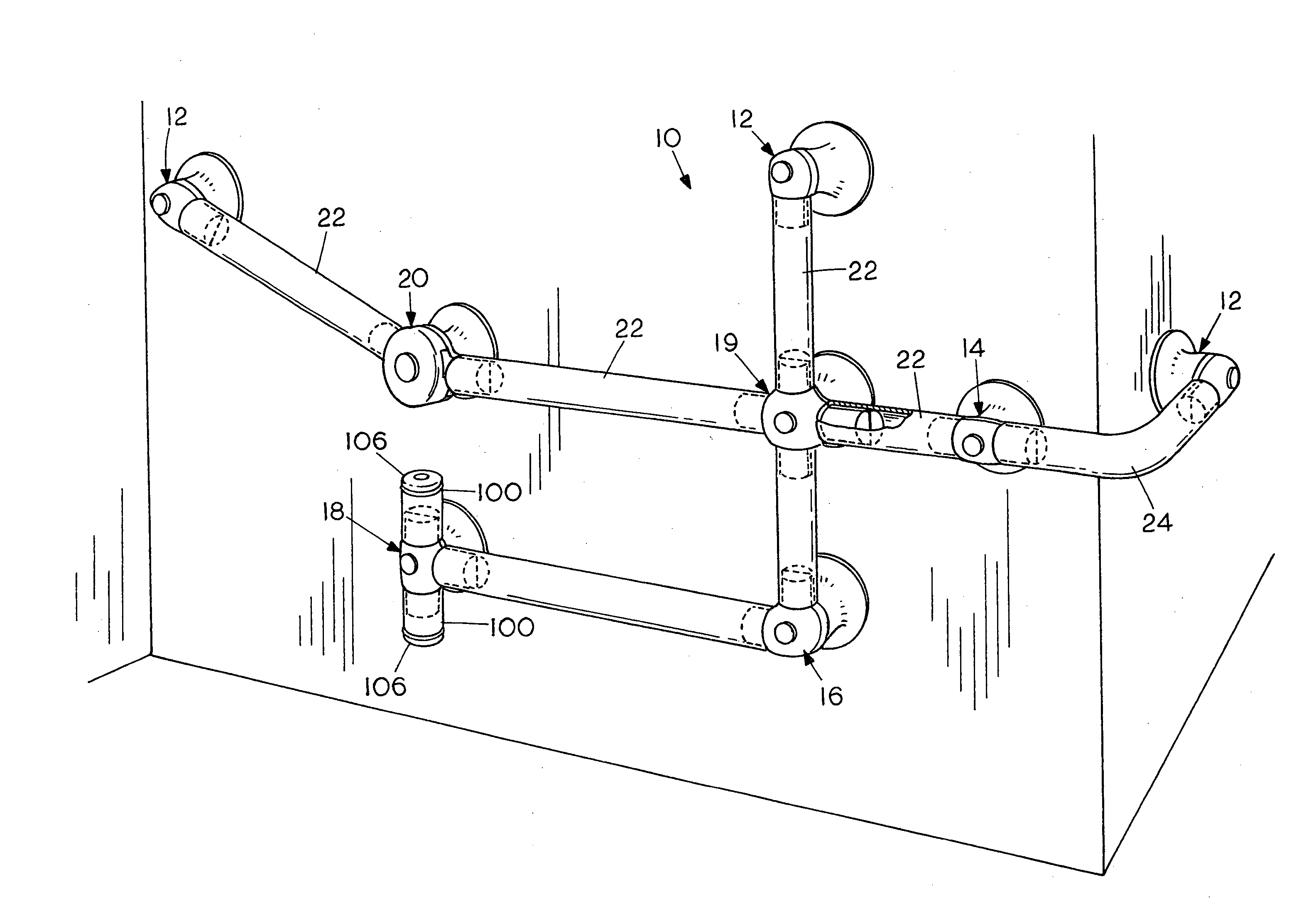
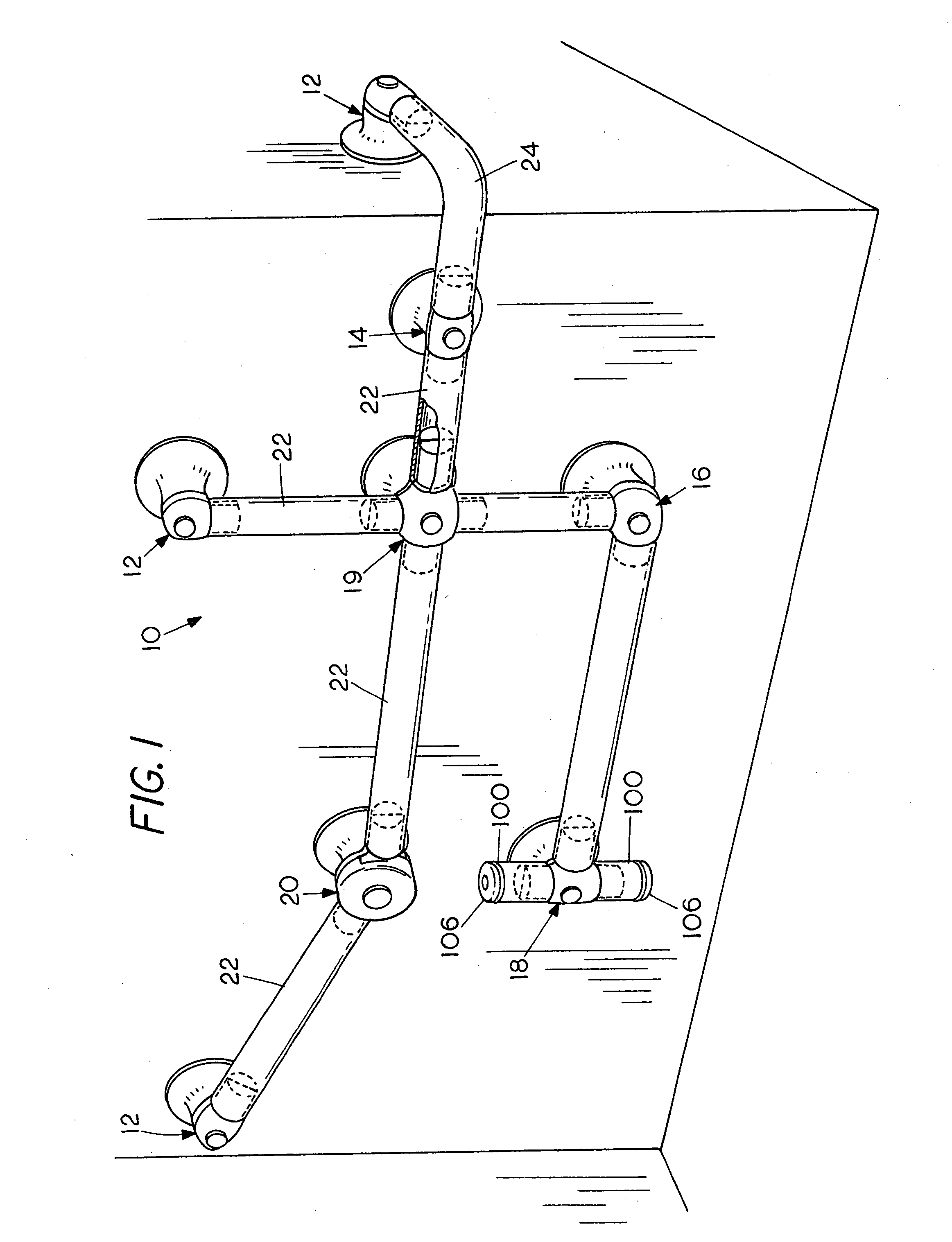
[0028] With reference to the Figures and particularly FIG. 1, a tubular grab railing and supporting connectors in accordance with the invention is indicated generally by the numeral 10. The supporting connectors, all of which embody the invention, must, as in any railing system, support different members of railing sections at various angles and accordingly are provided with different numbers of tubing support members. FIG. 1 shows by way of example, connectors embodying the invention can be used with different numbers of tubes and include the following: three end connectors designated 12, one straight connector 14, one L connector 16, one T connector 18, one X connector 19, and one adjustable connector 20. Mounted between the connectors 12-20 are sections of commercially available metal or plastic tubing 22 which may be pre-cut or cut to length by workmen on site during installation. A section of tubing 24 having a right angle bend that can be used as an inside or outside elbow is ...


PUM


Abstract

A reinforced connector for supporting a tubular grab railing has an upper tubing support that is aligned with the grab railing during use and a lower base portion which is attached to the tubing support, and is fastened a wall, floor, or other surface as a pedestal for the tubing support. The tubing support has an opening extending longitudinally thereof that divides it into upper and lower halves with the reinforcing plate held between them. The halves of the tubing support are aligned with one another to form at least one boss that is constructed and arranged to engage and support one end of a section of the grab railing tubing. The invention thus provides a composite connector assembly for supporting a section of grab railing; the composite connector being formed from dissimilar structural materials comprising an outer plastic resinous connector element with a relatively low thermal conductivity that is exposed to view and to tactile contact by the user and a hidden reinforcing plate which can be steel. Each boss is constructed and arranged to support one end of a section of the tubular grab railing. The reinforcing plate extends through the support to provide reinforcement for the tubing support including each boss and the tubing itself. An adjustable connector has two pivotally related portions with a joint that includes a pivot pin to permit angular adjustment on site. A corner elbow and end extension are also described.

Description

FIELD OF THE INVENTION [0001] This invention relates to railings and more particularly to safety railings that are commonly referred to as grab bars and to connectors therefor. BACKGROUND OF THE INVENTION [0002] Because of safety concerns, particularly in bathrooms and showers which may have wet floors that make it possible for a person to fall, and concern for physically impaired individuals, it has become common to provide safety railings often called grab bars in bathrooms and around showers and bathtubs. Grab bars are particularly helpful and are frequently required by building codes to aid physically impaired individuals. Applicable building codes include stringent strength requirements. Consequently, grab bar systems now in use are formed from metal such as stainless steel or aluminum in order to have the strength needed to meet code requirements and accordingly are relatively expensive and have decorative and aesthetic limitations. While plastic grab bars have been previously...

Claims


Application Information

Patent Timeline
Patent Type & Authority Applications(United States)
IPC IPC(8): F16B12/36
CPCA47K17/022E04F11/18Y10T403/42Y10T403/55E04F2011/1897E04F11/1808F16B2200/67
Inventor GOAD, EUGINE W.
Owner GOAD EUGINE W
Why Eureka
Try Eureka