Gas flow measuring apparatus

a technology of gas flow and measuring apparatus, which is applied in the direction of measurement devices, instruments, semiconductor devices, etc., can solve the problems of increasing the cost of the device, increasing the cost, and reducing the stress on the resistor on the diaphragm, so as to suppress the changes in the characteristics such as sensitivity and response, and reduce the stress on the resistor

Inactive Publication Date: 2007-04-26
HITACHI LTD
View PDF9 Cites 16 Cited by
  • Summary
  • Abstract
  • Description
  • Claims
  • Application Information

AI Technical Summary

Benefits of technology

[0020] In the gas flow measuring apparatus of the present invention, since only the stress mitigating means is formed, there can be implemented a gas flow measuring apparatus in which transmission of stress to the resistors on the diaphragm is reduced in the mounting stage without increasing the cost and it is possible to suppress changes in the characteristics such as the sensitivity and the response when th

Problems solved by technology

The diaphragm section on which the heating resistor is to be mounted is formed using a thin film and hence is easily distorted by stress, and although resistors formed using a polycrystalline silicon or a platinum film are employed for the thin film to form the detecting element, these resistors have a strain-resistance effect in which the resistance value changes with the stress strain.
Also, when a resin material and a resin adhesive are employed as package materials, stress change

Method used


Image

  • Gas flow measuring apparatus
  • Gas flow measuring apparatus
  • Gas flow measuring apparatus

Examples


first embodiment

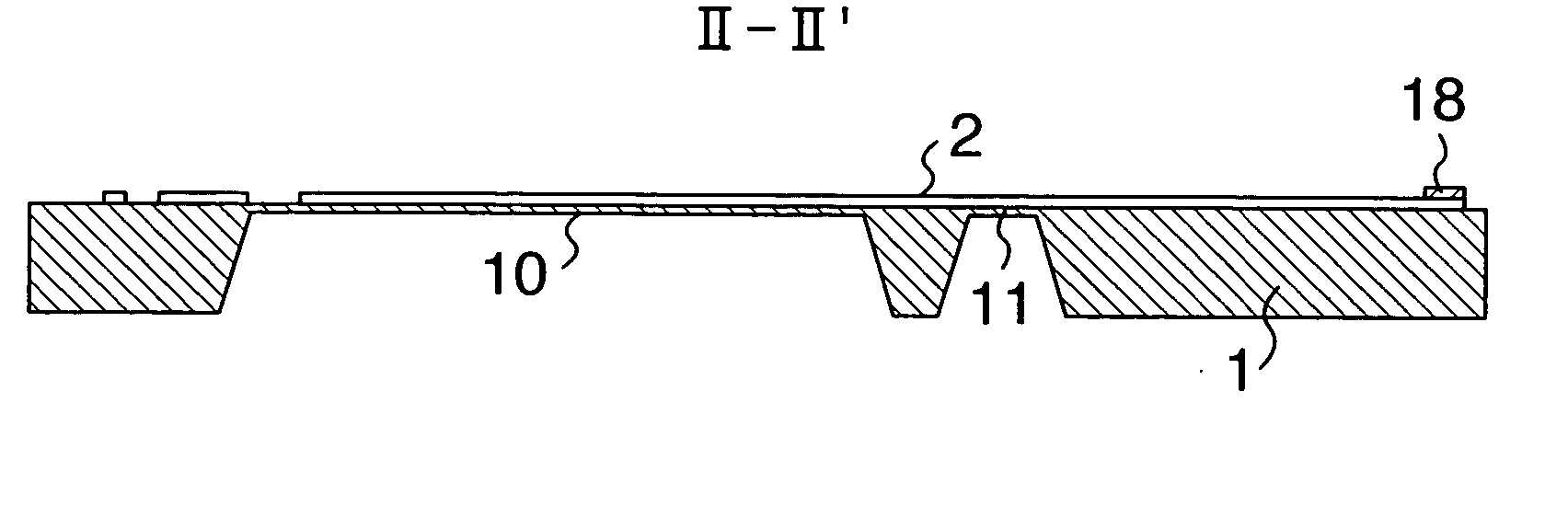
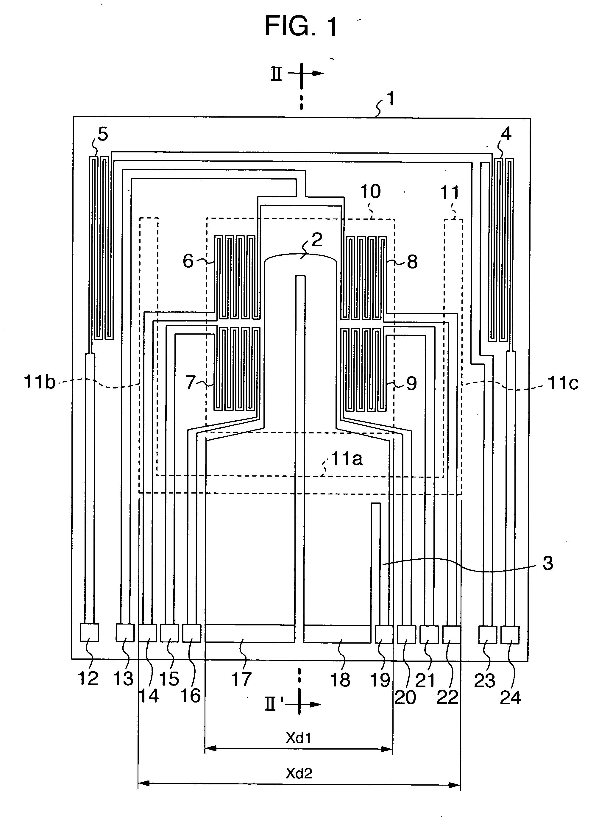
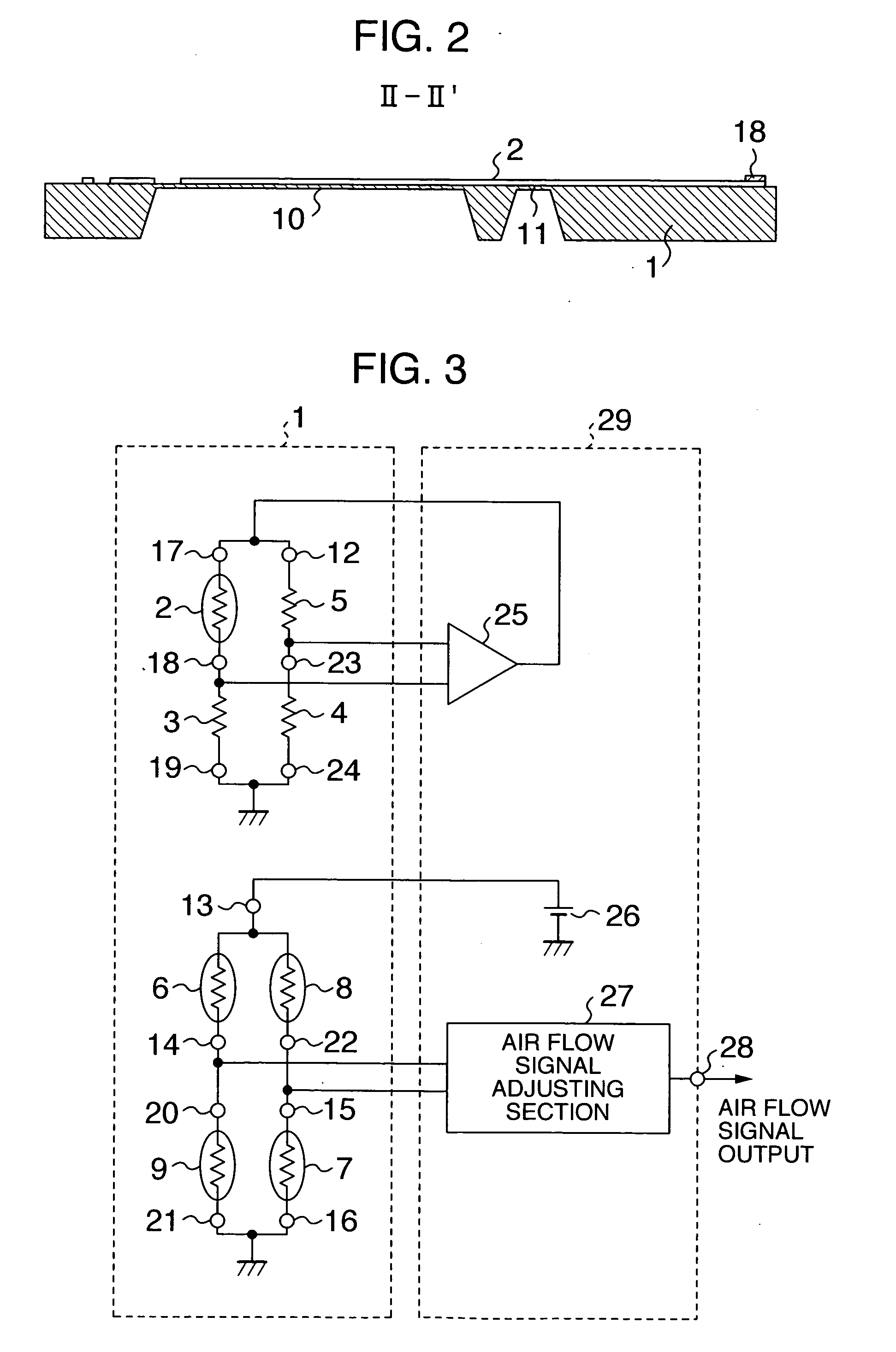
[0036]FIG. 1 is a diagram showing planar structure of a flow rate detecting element in an air flow measuring apparatus in a first embodiment of the present invention. FIG. 2 is a cross-sectional view along line II-II′ of FIG. 1.

[0037] In FIGS. 1 and 2, in a detecting element 1, a diaphragm 10 for the air flow rate detection worked and formed by an etching process using alkaline solvent or the like beginning at a rear surface of a substrate (first substrate) with a horizontal length of Xdl in the diagrams (outer diameter size of the diaphragm). On the diaphragm 10, a heating resistor 2 as a detecting resistor, upstream-side thermo-sensitive resistors 6 and 7, and downstream-side thermo-sensitive resistors 8 and 9 are disposed.

[0038] On the substrate in the periphery of the diaphragm 10, fixed resistors 3 and 4 and a temperature measuring resistor 5 are formed. These resistors are fabricated using a platinum film and / or a polycrystalline silicon film of which the resistance value ch...

second embodiment

[0059]FIG. 7 is a diagram showing planar structure of a flow rate detecting element in the air flow measuring apparatus in a second embodiment of the present invention. The second embodiment is an example in which, as compared with the first embodiment shown in FIG. 1, the shape of the groove 11 is changed from the “inverse-C” shape to the “I” shape and only the horizontal 11a is disposed. The other structure is equal to that of the example of FIG. 1.

[0060] By using the groove shape as shown in FIG. 7, the mounting stress reduction can be achieved using the minimum required working area, and hence the strain influence can be suppressed without lowering strength.

third embodiment

[0061]FIG. 8 is a diagram showing planar structure of a flow rate detecting element in the air flow measuring apparatus in a third embodiment of the present invention. FIG. 9 is a cross-sectional view along line V-V′ of FIG. 4 of the air flow measuring apparatus in a third embodiment.

[0062] The third embodiment is implemented by changing the “inverse-C” shape of the first embodiment shown in FIG. 1 to a shape to surround the entire periphery of the diaphragm 10, and a horizontal groove 11d is added. The other structure is equal to that of the example of FIG. 1.

[0063] By using the groove shape of this kind, the strain influence can be suppressed in the mounting structure in which the detecting element is fixed onto the board 56 by the adhesive 64 not only in the area in which the terminals 12 to 24 are formed, but also in the tip end section of the detecting element 1 (the edge section area opposing to the fixed section area with the diaphragm 10 and the horizontal groove 11d there...


PUM


Abstract

A gas flow measuring apparatus includes a detecting element including a heating resistor and a thermo-sensitive resistor disposed on a diaphragm and external terminals connected to the heating resistor and the thermo-sensitive resistor, and a flow rate detecting unit which controls heating temperature of the heating resistor and which detects a flow rate of gas according to a change in a resistance value of the heating resistor or the thermo-sensitive resistor. The detecting element includes a resistor area in which the heating resistor and the thermo-sensitive resistor are formed and a fixed section area in which the external terminals are formed. A stress mitigating unit is formed between the resistor area and the fixed section area.

Description

BACKGROUND OF THE INVENTION [0001] The present invention relates to a flow meter to measure a gas flow rate, and in particular, to a gas flow measuring apparatus suitable to detect an air flow rate sucked by an engine of a car. [0002] There have been known an intake air flow meter of an engine of a car as an example of a gas flow measuring apparatus of a method in which a heating control current value of a heating resistor is detected to be converted into an air flow rate and an intake air flow meter of a method in which thermal influences on thermo-sensitive resistors disposed in the upstream and the downstream of a resistor are detected as a temperature difference signal to obtain the signal as a voltage of a bridge circuit. [0003] In this connection, to detect the intake air flow rate to a car engine, it is required that the characteristics should be stable in consideration of the following conditions and environments. [0004] (1) Consideration for characteristic variations due to...

Claims


Application Information

Patent Timeline
IPC IPC(8): G01F1/68
CPCG01F1/6845G01F1/692H01L2924/0002H01L2924/00
Inventor HANZAWA, KEIJISHIMADA, SATOSHIYASUKAWA, AKIOSAITO, NAOKINAKADA, KEIICHIWATANABE, IZUMI
Owner HITACHI LTD
Why Eureka
Try Eureka