Drive mechanisms suitable for use in drug delivery devices

a technology of driving mechanism and drug delivery device, which is applied in the direction of infusion needles, infusion syringes, other medical devices, etc., can solve the problems of physical infirmity, impaired vision, and the inability to easily correct a set overdose,

Active Publication Date: 2007-04-26
SANOFI AVENTIS DEUT GMBH
View PDF98 Cites 114 Cited by
  • Summary
  • Abstract
  • Description
  • Claims
  • Application Information

AI Technical Summary

Benefits of technology

[0020] The term “housing” according to instant invention shall preferably mean any exterior housing (“main housing”, “body”, “shell”) or interior housing (“insert”, “inner body”) having a helical thread. The housing may be designed to enable the safe, correct, and comfortable handling of the drug delivery device or any of its mechanism. Usually, it is designed to house, fix, protect, guide, and / or engage with any of the inner components of the drug delivery device (e.g., the drive mechanism, cartridge, plunger, piston rod) by limiting the exposure to contaminants, such as liquid, dust, dirt etc. In general, the housing may be unitary or a multipart component of tubular or non-tubular shape. Usually, the exterior housing serves to house a cartridge from which a number of doses of a medicinal product may by dispensed.

Problems solved by technology

In the case of those with diabetes, many users will be physically infirm and may also have impaired vision requiring the drive mechanism to have low dispensing force and an easy to read dose setting display.
Whilst this device provides many improvements over the prior art the easy correction of a set overdose remains unresolved without either dispensing the set amount of fluid or dismantling the cartridge.

Method used


Image

  • Drive mechanisms suitable for use in drug delivery devices
  • Drive mechanisms suitable for use in drug delivery devices
  • Drive mechanisms suitable for use in drug delivery devices

Examples


example 1

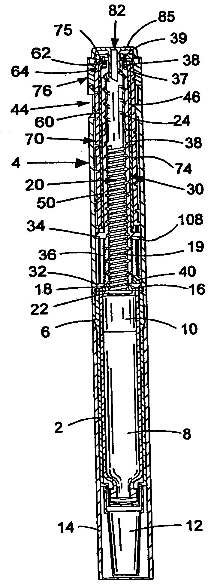
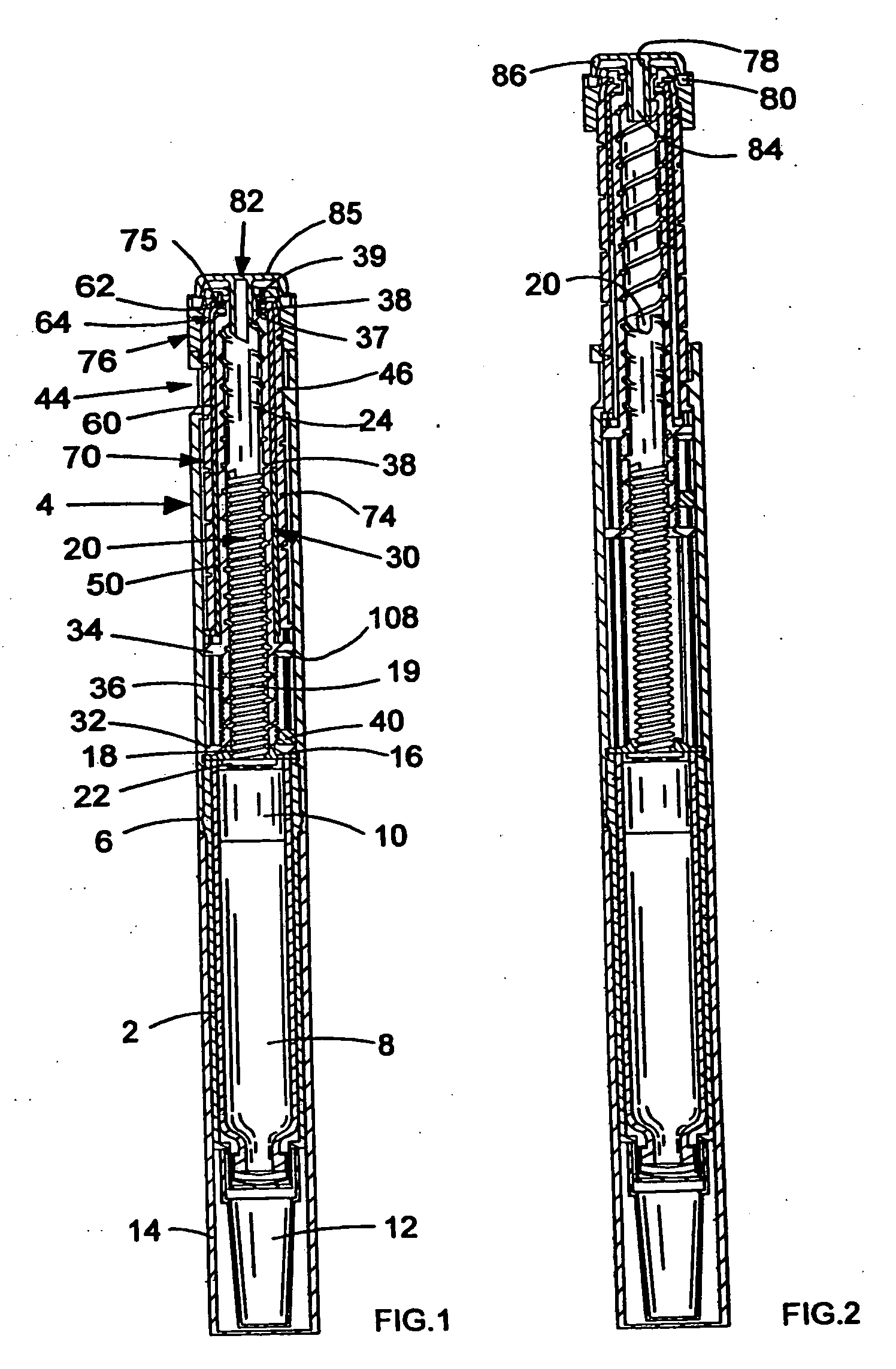
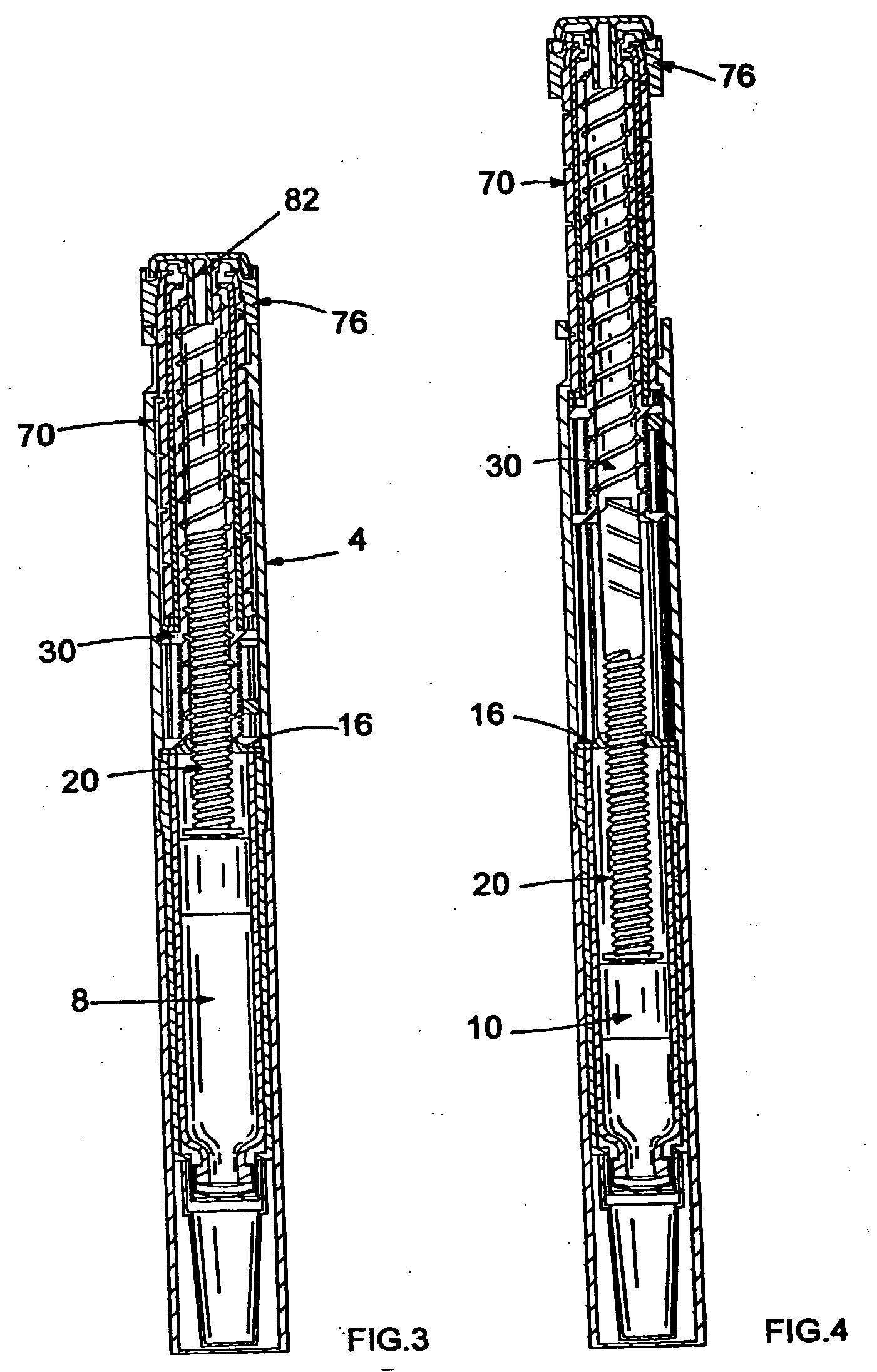
[0076] Referring first to FIGS. 1 to 5, there is shown a drug delivery device in accordance with the present invention in a number of positions.

[0077] The drug delivery device comprises a housing having a first cartridge retaining part 2, and second main (exterior) housing part 4. A first end of the cartridge retaining means 2 and a second end of the main housing 4 are secured together by retaining features 6. In the illustrated embodiment, the cartridge retaining means 2 is secured within the second end of the main housing 4.

[0078] A cartridge 8 from which a number of doses of a medicinal product may be dispensed is provided in the cartridge retaining part 2. A piston 10 is retained in a first end of the cartridge 8.

[0079] A removable cap 12 is releasably retained over a second end of the cartridge retaining part 2. In use the removable cap 12 can be replaced by a user with a suitable needle unit (not shown). A replacable cap 14 is used to cover the cartridge retaining part 2 ex...

example 2

[0108] In another embodiment of the invention (FIG. 17) there is seen a drive mechanism comprising a second main housing 4′ having a first end and a second end. A cartridge, containing medicinal product, can be mounted to the first end of the second main housing 4′ and retained by any suitable means. The cartridge and its retaining means are not shown in the illustrated embodiment. The cartridge may contain a number of doses of a medicinal product and also typically contains a displaceable piston. Displacement of the piston causes the medicinal product to be expelled from the cartridge via a needle (also not shown).

[0109] In the illustrated embodiment, an insert 16′ is provided within the main housing 4′. The insert 16′ is secured against rotational and axial motion with respect to the second main housing 4′. The insert 16′ is provided with a threaded circular opening extending therethrough. Alternatively, the insert may be formed integrally with the second main housing 4′.

[0110] ...

example 3

[0131] Referring to FIGS. 18 to 22 there may be seen a drug delivery device in accordance with the present invention. The drug delivery device comprises a two-part housing 2″ within which are located a cartridge 4″ containing a medicinal product, means for setting or selecting the dose of medicinal product to be expelled and means for expelling the selected dose of medicinal product. The housing 2″ is generally cylindrical in shape and houses a rack 6″ to be described in more detail below. The cartridge 4″ is located within a first part 8″ of the housing 2″. The dose setting means and the means for expelling the selected dose of medicinal product are retained, that is held, within a second part 10″ of the housing 2″. The first part 8″ of the housing 2″ and the second part 10″ of the housing 2″ may be secured together by any suitable means.

[0132] The cartridge 4″ may be secured in position in the first part 8″ of the housing 2″ by any suitable means. A needle unit may be secured to ...


PUM


Abstract

A drive mechanism suitable for use in drug delivery devices is disclosed. The drive mechanism may be used with injector-type drug delivery devices, such as those permitting a user to set the delivery dose. The drive mechanism may include a housing, a dose dial sleeve, and a drive sleeve. A clutch is configured to permit rotation of the drive sleeve and the dose dial sleeve with respect to the housing when the dose dial sleeve and drive sleeve are coupled through the clutch. Conversely, when the dose dial sleeve and drive sleeve are in a de-coupled state, rotation of the dose dial sleeve with respect to the housing is permitted and rotation of the drive sleeve with respect to the housing is prevented. In the de-coupled state, axial movement of the drive sleeve transfers force in a longitudinal direction for actuation of a drug delivery device.

Description

THE TECHNICAL FIELD OF THE INVENTION [0001] The present invention relates to drive mechanisms suitable for use in drug delivery devices, in particular pen-type injectors, having dosage setting means, enabling the administration of medicinal products from a multi-dose cartridge. In particular, the present invention relates to such drug delivery devices where a user may set the dose. DESCRIPTION OF RELATED ART [0002] Such drug delivery devices have application where regular injection by persons without formal medical training occurs, i.e., patients. This is increasingly common amongst those having diabetes where self-treatment enables such persons to conduct effective management of their diabetes. [0003] These circumstances set a number of requirements for drug delivery devices of this kind. The device must be robust in construction, yet easy to use in terms of the manipulation of the parts, understanding by a user of its operation and the delivery of the required dose of medicament. ...

Claims


Application Information

Patent Timeline
Patent Type & Authority Applications(United States)
IPC IPC(8): A61M5/00A61M5/24A61M5/315
CPCA61M5/24A61M5/31535A61M5/31541A61M5/31551A61M5/3156A61M5/31575A61M5/31536A61M2005/2407A61M2205/581A61M2205/582A61M5/31533A61M5/31578A61M5/31565A61M5/31585A61M5/315A61M5/31546A61M5/31528A61M5/31563A61M5/31568A61M5/3157A61M5/31593A61M5/32A61M2005/3126
Inventor VEASEY, ROBERT FREDERICKPERKINS, ROBERTPLUMPTRE, DAVID AUBREY
Owner SANOFI AVENTIS DEUT GMBH
Why Eureka
Try Eureka