
Drive assembly suitable for use in a drug delivery device and drug delivery device

a technology of drive assembly and drug delivery device, which is applied in the direction of intravenous device, medical syringe, infusion syringe, etc., can solve the problem of not being intended to provide information, and achieve the effect of translational movement of the piston rod along the axis

Active Publication Date: 2014-11-11
SANOFI AVENTIS DEUT GMBH
View PDF4 Cites 1 Cited by
  • Summary
  • Abstract
  • Description
  • Claims
  • Application Information

AI Technical Summary

Benefits of technology

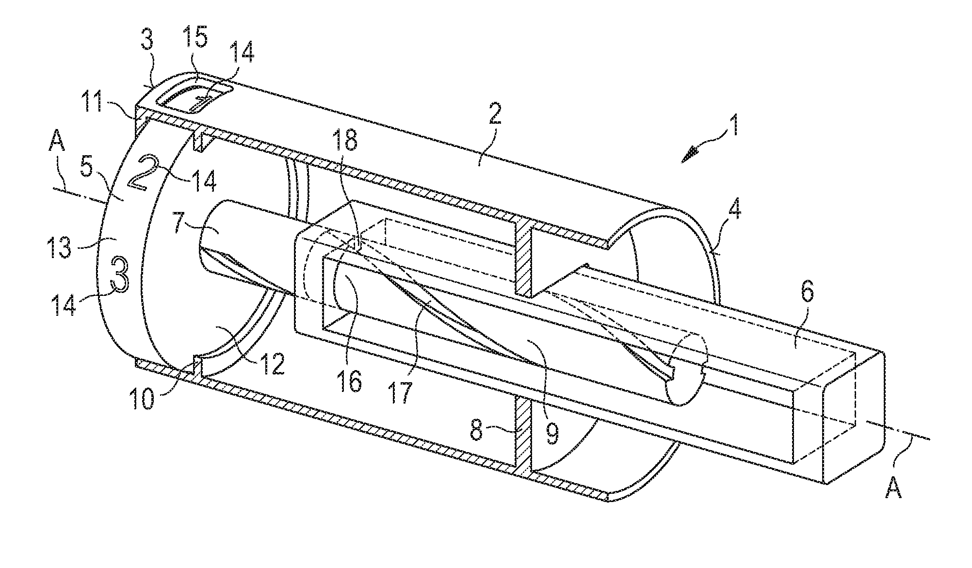
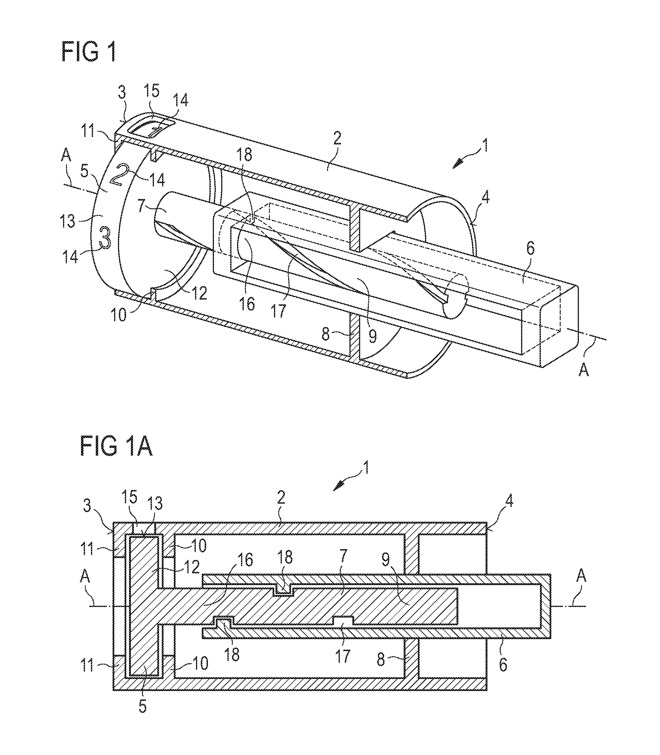
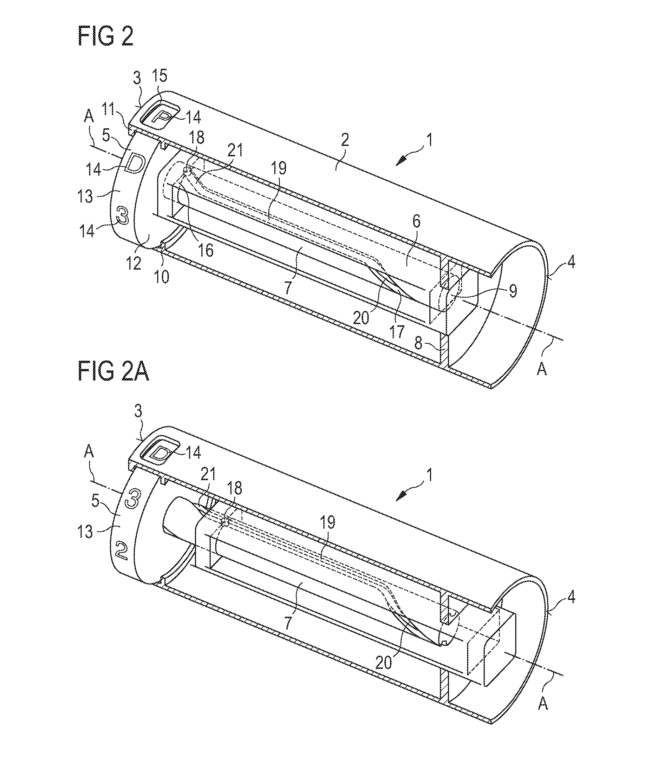
[0023]According to at least one aspect at least a part of the rotation member is arranged between the piston rod and the axis. At least a part of the rotation member or the rotation member and, preferably, the indicator may be arranged within the piston rod. This arrangement of the rotation member allows for facilitated implementation of the indicator in a drive assembly that has driving elements that are arranged on the outside of the piston rod, like elements that mechanically contact the housing, for example by engaging the housing. Additionally, an arrangement of the rotation member nearer to the axis than the piston rod facilitates a compact design of the drive assembly. Furthermore, the degrees of freedom on where to arrange the indicator in the drive assembly are increased, because the part of the rotation member may be arranged between the piston rod and the axis. Preferably, that part of the rotation member which is arranged within the piston rod is also provided to interact with the piston rod for converting movement of the piston rod with respect to the housing into rotational movement of the indicator. Consequently, coupling between rotation member and piston rod can be achieved via the rotation member from within the piston rod, for example by engagement and / or mechanical interaction of piston rod and indicator. An external feature on the outside of the rotation member, e.g. on an outer wall, may be arranged to mechanically interact with an internal feature provided within, e.g. on an inner wall of, the piston rod. If the rotation member or the indicator was arranged completely outside of the piston rod, for example as an indicator sleeve surrounding the piston rod, it would be necessary for the indicator to be arranged near the distal end of the housing in such a way that the piston rod which travels through the indicator can still couple to the indicator even if the piston rod has already moved a considerable distance in the distal direction. This can be avoided on account of the rotation member, because the rotation member can be configured to couple piston rod and indicator, whereas a different indicator part of the indicator can be used for providing (displaying) information.
[0090]The term “housing” shall preferably mean any exterior housing (“main housing”, “body”, “shell”) or interior housing (“insert”, “inner body”), e.g. having a unidirectional axial coupling to prevent proximal movement of specific components. The housing may be designed to enable the safe, correct, and comfortable handling of the drug delivery device or any of its mechanism(s). Usually, it is designed to house, fix, protect, guide, and / or engage with any of the inner components of the drug delivery device (e.g., the drive assembly, cartridge, plunger, piston rod) by limiting the exposure to contaminants, such as liquid, dust, dirt etc. In general, the housing may be unitary or a multipart component of tubular or non-tubular shape. Usually, the exterior housing serves to house a cartridge from which a number of doses of a medicinal product may by dispensed. Preferably, the exterior housing is provided with a plurality of maximum dose stops adapted to be abutted by an axial stop provided on the drive member. The piston rod may be coupleable or coupled to the housing.

Problems solved by technology

Thus, this device is not intended for providing information about a number of doses.

Method used


Image

  • Drive assembly suitable for use in a drug delivery device and drug delivery device
  • Drive assembly suitable for use in a drug delivery device and drug delivery device
  • Drive assembly suitable for use in a drug delivery device and drug delivery device

Examples


first embodiment

[0170]As compared to the first embodiment, one region or a plurality of regions of the (helical) thread formed on rotation member 7 can be replaced by a region that runs parallel to axis A, with the indicator not rotating while the rotation member is coupled to the piston rod in the region that runs parallel to axis A.

[0171]FIG. 3 shows an oblique sectional view of a third embodiment of the drive assembly 1. The third embodiment essentially corresponds to the embodiment described in conjunction with FIGS. 1 and 1A.

third embodiment

[0172]In contrast thereto, the drive assembly 1 comprises a plurality of indication surfaces, which are arranged side by side along the axis A. For example, indicator 5 comprises two indication surfaces 13 and 22. Each of those indication surfaces can be provided with a plurality of index elements 14. Indication surfaces 13 and 22 may be non-rotatable relative to one another.

[0173]In this embodiment, the indicator 5, in particular indicator part 12 thereof, which comprises indication surfaces 13 and 22, is threadedly coupled to the housing 2. Preferably, indicator 5 is threadedly engaged to the housing 2. Housing 2 can comprise a (helical) thread 23 that engages a (helical) thread 24 of indicator part 12.

[0174]If the indicator 5 rotates, the indication surface 22 can be rotated into indication position and replace indication surface 13 in this position. That is to say, indication surface 13 can be rotated away from the window and indication surface 22 can be moved under the window,...

fourth embodiment

[0180]FIG. 4 shows an oblique sectional view of the drive assembly 1. The drive assembly shown in FIG. 4 essentially corresponded to the one described in conjunction with FIG. 3.

[0181]In contrast thereto, indicator 5 comprises two indicator parts 12 and 25 which can be rotated with respect to one another. Indicator part 12 can comprise indication surface 13. Indicator part 25 can comprise indication surface 22. Both indication surfaces 13 and 22 are visible from the outside through window 15.

[0182]Indication surfaces 22 and 13 are rotatable relative to one another. Indicator parts 12 and 25 may be coupled to one another via an odometer(-like) mechanism. A rotation by a predetermined angle, for example a full rotation about 360°, of indicator part 12 relative to indicator part 25 may cause indicator part 25 to rotate, preferably about an angle smaller than the predetermined angle, such that the next index element 14 of indication surface 22 is rotated into indication position.

[0183]I...


PUM


Abstract

A drive assembly for use in a drug delivery device is proposed, the drive assembly comprising: a housing having a proximal end and a distal end; an axis extending between the proximal end and the distal end; at least one drive member; a piston rod adapted to be driven along the axis by the drive member; an indicator adapted to provide positional information about a position of the piston rod relative to the proximal end, wherein the indicator and the piston rod are configured to convert a movement of the piston rod with respect to the housing into a rotational movement of the indicator. Additionally, a drug delivery device comprising the drive assembly is provided for.

Description

CROSS REFERENCE TO RELATED APPLICATIONS[0001]The present application claims priority to International Application No. PCT / EP2009 / 003310 filed on May 9, 2009, which claims the priority of European patent applications EP 08009260.4, filed on May 20, 2008, and EP 08011676.7 filed on Jun. 27, 2008. The entire disclosure content of these applications is herewith incorporated by reference into the present application.TECHNICAL FIELD[0002]The present invention relates to a drive assembly suitable for use in a drug delivery device, preferably a pen-type injector, by which a number of pre-set doses of a medicinal product can be administered. In particular, the present invention relates to such a drug delivery device where a user may activate the drug delivery device.PRIOR ART[0003]Such drug delivery devices have application where persons without formal medical training, i.e., patients, need to administer an accurate and predefined dose of a medicinal product, such as heparin or insulin. In p...

Claims


Application Information

Patent Timeline
Patent Type & Authority Patents(United States)
IPC IPC(8): A61M5/315A61M5/00A61M5/31
CPCA61M5/31541A61M2005/3125A61M5/31593A61M2005/3126A61M2005/3152A61M5/31551A61M5/31555
Inventor JONES, MATTHEW MEREDITHPLUMPTRE, DAVID AUBREY
Owner SANOFI AVENTIS DEUT GMBH
Learn More